


55
1745D–ATARM–04-Nov-05
AT91M55800A
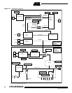
12.2 Slow Clock Generator
The AT91M55800A has a very low power 32 kHz oscillator powered by the backup battery
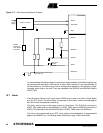
voltage supplied on the VDDBU pins. The XIN32 and XOUT32 pins must be connected to a
32768 Hz crystal. The oscillator has been especially designed to connect to a 6 pF typical load
capacitance crystal and does not require any external capacitor, as it integrates the XIN32 and
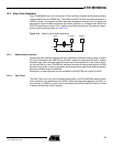
XOUT32 capacitors to ground. For a higher typical load capacitance, two external capaci-
tances must be wired as shown in Figure 12-3:
Figure 12-3. Higher Typical Load Capacitance
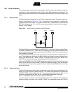
12.2.1 Backup Reset Controller
The backup reset controller initializes the logic supplied by the backup battery power. A simple
RC circuit connected to the NRSTBU pin provides a power-on reset signal to the RTC and the
shutdown logic. When the reset signal increases and as the startup time of the 32 kHz oscilla
-
tor is around 300 ms, the AT91M55800A maintains the internal backup reset signal for 32768
oscillator clock cycles in order to guarantee the backup power supplied logic does not operate
before the oscillator output is stabilized.
Alternatively, a reset supervisor can be connected to the NRSTBU pin in place of the RC.
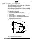
12.2.2 Slow Clock
The Slow Clock is the only clock considered permanent in an AT91M55800A-based system
and is essential in the operations of the APMC (Advanced Power Management Controller). In
any use-case, a 32768 Hz crystal must be connected to the XIN32 and XOUT32 pins in order
to ensure that the Slow Clock is present.
XIN32 XOUT32 GNDPLL
C
L2
C
L1