


56
1745D–ATARM–04-Nov-05
AT91M55800A
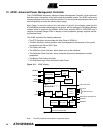
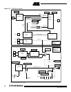
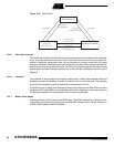
12.3 Clock Generator
The clock generator consists of the main oscillator, the PLL and the clock selection logic with
its prescaler. It aims at selecting the Master Clock, called MCK throughout this datasheet. The
clock generator also contains the circuitry needed to drive the MCKO pin with the master clock
signal.
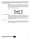
12.3.1 Main Oscillator
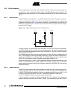
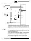
The Main Oscillator is designed for a 3 to 20 MHz fundamental crystal. The typical crystal con-
nection is illustrated in Figure 12-4. The 1 kΩ resistor is only required for crystals with
frequencies lower than 8 MHz. The oscillator contains 25 pF capacitances on each XIN and
XOUT pin. Consequently, CL1 and CL2 can be removed when a crystal with a load capaci-
tance of 12.5 pF is used.
Figure 12-4. Typical Crystal Connection of Main Oscillator
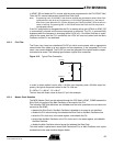
The Main Oscillator can be bypassed if the MOSCBYP bit in the Clock Generator Mode Regis-
ter (APMC_CGMR) is set to 1. In this case, any frequency (up to the maximum specified in the
electrical characteristics datasheet) can be input on the XIN pin. If the PLL is used, a minimum
input frequency is required.
To minimize the power required to start up the system, the Main Oscillator is disabled after the
reset. The software can deactivate the Main Oscillator to reduce the power consumption by
clearing the MOSCEN bit in APMC_CGMR. The MOSCS (Main Oscillator Status) bit in
APMC_SR is automatically cleared, indicating that the Main Oscillator is off.
Writing the MOSCEN bit in APMC_CGMR reactivates the Main Oscillator and loads the value
written in the OSCOUNT field in APMC_CGMR in the oscillator counter. Then, the oscillator
counter decrements every 8 clock cycles and when it reaches 0, the MOSCS bit is set and can
provide an interrupt.
12.3.2 Phase Lock Loop
The Main Oscillator output signal feeds the phase lock loop, which aims at multiplying the fre-
quency of its input signal by a number up to 64. This number is programmed in the MUL field
of APMC_CGMR and the multiplication ratio is the programmed value plus one (MUL+1). If a
null value is programmed into MUL, the PLL is automatically disabled to save power.
The PLL is disabled at reset to minimize the power consumption.
A start-up sequence must be executed to enable the PLL if it is disabled. This sequence is
started by writing a new MUL value in APMC_CGMR. This automatically clears the LOCK bit
XIN XOUT GNDPLL
C
L2
C
L1
1KΩ