


18
1745D–ATARM–04-Nov-05
AT91M55800A
8. Peripherals
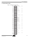
The AT91M55800A peripherals are connected to the 32-bit wide Advanced Peripheral Bus.
Peripheral registers are only word accessible – byte and half-word accesses are not sup-
ported. If a byte or a half-word access is attempted, the memory controller automatically
masks the lowest address bits and generates a word access.
Each peripheral has a 16-Kbyte address space allocated (the AIC only has a 4-Kbyte address
space).
8.1 Peripheral Registers
The following registers are common to all peripherals:
• Control Register – Write-only register that triggers a command when a one is written to the
corresponding position at the appropriate address. Writing a zero has no effect.
• Mode Register – read/write register that defines the configuration of the peripheral. Usually
has a value of 0x0 after a reset.
• Data Register – read and/or write register that enables the exchange of data between the
processor and the peripheral.
• Status Register – Read-only register that returns the status of the peripheral.
• Enable/Disable/Status Registers – shadow command registers. Writing a one in the Enable
Register sets the corresponding bit in the Status Register. Writing a one in the Disable
Register resets the corresponding bit and the result can be read in the Status Register.
Writing a bit to zero has no effect. This register access method maximizes the efficiency of
bit manipulation, and enables modification of a register with a single non-interruptible
instruction, replacing the costly read-modify-write operation.
Unused bits in the peripheral registers are shown as “–” and must be written at 0 for upward
compatibility. These bits read 0.
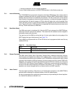
8.2 Peripheral Interrupt Control
The Interrupt Control of each peripheral is controlled from the status register using the inter-
rupt mask. The status register bits are ANDed to their corresponding interrupt mask bits and
the result is then ORed to generate the Interrupt Source signal to the Advanced Interrupt
Controller.
The interrupt mask is read in the Interrupt Mask Register and is modified with the Interrupt
Enable Register and the Interrupt Disable Register. The enable/disable/status (or mask)
makes it possible to enable or disable peripheral interrupt sources with a non-interruptible sin-
gle instruction. This eliminates the need for interrupt masking at the AIC or Core level in real-
time and multi-tasking systems.
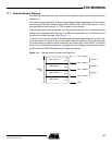
8.3 Peripheral Data Controller
An on-chip, 8-channel Peripheral Data Controller (PDC) transfers data between the on-chip
USARTs/SPI and the on and off-chip memories without processor intervention. One PDC
channel is connected to the receiving channel and one to the transmitting channel of each
USART and SPI.
The user interface of a PDC channel is integrated in the memory space of each peripheral. It
contains a 32-bit address pointer register and a 16-bit count register. When the programmed
data is transferred, an end of transfer interrupt is generated by the corresponding peripheral.