


137
1745D–ATARM–04-Nov-05
AT91M55800A
18.4 Transmitter
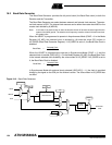
The transmitter has the same behavior in both synchronous and asynchronous operating
modes. Start bit, data bits, parity bit and stop bits are serially shifted, lowest significant bit first,
on the falling edge of the serial clock. See example in Figure 18-6.
The number of data bits is selected in the CHRL field in US_MR.
The parity bit is set according to the PAR field in US_MR.
The number of stop bits is selected in the NBSTOP field in US_MR.
When a character is written to US_THR (Transmit Holding), it is transferred to the Shift Regis-
ter as soon as it is empty. When the transfer occurs, the TXRDY bit in US_CSR is set until a
new character is written to US_THR. If Transmit Shift Register and US_THR are both empty,
the TXEMPTY bit in US_CSR is set.
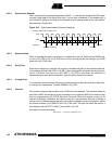
18.4.1 Time-guard
The Time-guard function allows the transmitter to insert an idle state on the TXD line between
two characters. The duration of the idle state is programmed in US_TTGR (Transmitter Time-
guard). When this register is set to zero, no time-guard is generated. Otherwise, the transmit-
ter holds a high level on TXD after each transmitted byte during the number of bit periods
programmed in US_TTGR.
18.5 Multi-drop Mode
When the field PAR in US_MR equals 11X (binary value), the USART is configured to run in
multi-drop mode. In this case, the parity error bit PARE in US_CSR is set when data is
detected with a parity bit set to identify an address byte. PARE is cleared with the Reset Sta-
tus Bits Command (RSTSTA) in US_CR. If the parity bit is detected low, identifying a data
byte, PARE is not set.
The transmitter sends an address byte (parity bit set) when a Send Address Command
(SENDA) is written to US_CR. In this case, the next byte written to US_THR will be transmit-
ted as an address. After this any byte transmitted will have the parity bit cleared.
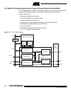
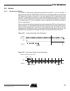
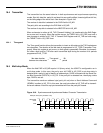
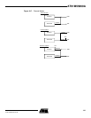
Figure 18-6. Synchronous and Asynchronous Modes: Character Transmission
Idle state duration
between two characters
Time-guard
value
Bit
period
•=
D0 D1 D2 D3 D4 D5 D6 D7
TXD
Start
Bit
Parity
Bit
Stop
Bit
Example: 8-bit, parity enabled 1 stop
Baud Rate
Clock