


160
1745D–ATARM–04-Nov-05
AT91M55800A
19.2 Timer Counter Description
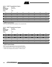
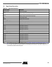
Each Timer Counter channel is identical in operation. The registers for channel programming
are listed in Table 19-1 on page 159.
19.2.1 Counter
Each Timer Counter channel is organized around a 16-bit counter. The value of the counter is
incremented at each positive edge of the input clock. When the counter reaches the value
0xFFFF and passes to 0x0000, an overflow occurs and the bit COVFS in TC_SR (Status Reg-
ister) is set.
The current value of the counter is accessible in real-time by reading TC_CV. The counter can
be reset by a trigger. In this case, the counter value passes to 0x0000 on the next valid edge
of the clock.
19.2.2 Clock Selection
At block level, input clock signals of each channel can either be connected to the external
inputs TCLK0, TCLK1 or TCLK2, or be connected to the configurable I/O signals TIOA0,
TIOA1 or TIOA2 for chaining by programming the TC_BMR (Block Mode).
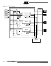
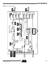
Each channel can independently select an internal or external clock source for its counter:
• Internal clock signals: MCK/2, MCK/8, MCK/32, MCK/128, MCK/1024
• External clock signals: XC0, XC1 or XC2
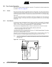
The selected clock can be inverted with the CLKI bit in TC_CMR (Channel Mode). This allows
counting on the opposite edges of the clock.
The burst function allows the clock to be validated when an external signal is high. The
BURST parameter in the Mode Register defines this signal (none, XC0, XC1, XC2).
Note: In all cases, if an external clock is used, the duration of each of its levels must be longer than the
system clock (MCK) period. The external clock frequency must be at least 2.5 times lower than
the system clock.
Figure 19-2. Clock Selection
MCK/2
MCK/8
MCK/32
MCK/128
MCK/1024
XC0
XC1
XC2
CLKS
CLKI
BURST
1
Selected
Clock