


66
1745D–ATARM–04-Nov-05
AT91M55800A
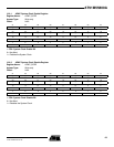
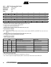
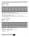
12.9.7 APMC Clock Generator Mode Register
Register Name: APMC_CGMR
Access Type: Read/Write
Reset Value: 0x0
Offset: 0x20
• MOSCBYP: Main Oscillator Bypass (Code Label APMC_MOSC_BYP)
0 = Crystal must be connected between XIN and XOUT.
1 = External clock must be provided on XIN.
• MOSCEN: Main Oscillator Enable (Code Label APMC_MOSC_EN)
0 = Main Oscillator is disabled.
1 = Main Oscillator is enabled.
Note: When operating in Bypass Mode, the Main Oscillator must be disabled. MOSCEN and MOSCBYP bits must never be set
together.
• MCKODS: Master Clock Output Disable (Code Label APMC_MCKO_DIS)
0 = The MCKO pin is driven with the Master Clock (MCK).
1 = The MCKO pin is tri-stated.
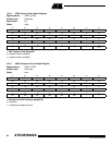
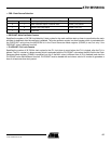
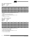
• PRES: Prescaler Selection
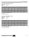
• MUL: Phase Lock Loop Factor
0 = The PLL is deactivated, reducing power consumption to a minimum.
1 - 63 = The PLL output is at a higher frequency (MUL+1) than the input if the bit lock is set in APMC_SR.
31 30 29 28 27 26 25 24
––
PLLCOUNT
23 22 21 20 19 18 17 16
OSCOUNT
15 14 13 12 11 10 9 8
CSS MUL
76543210
–
PRES
–
MCKODS MOSCEN MOSCBYP
PRES Prescaler Selected Code Label
0 0 0 None. Prescaler Output is the selected clock. APMC_PRES_NONE
0 0 1 Selected clock is divided by 2 APMC_PRES_DIV2
0 1 0 Selected clock is divided by 4 APMC_PRES_DIV4
0 1 1 Selected clock is divided by 8 APMC_PRES_DIV8
1 0 0 Selected clock is divided by 16 APMC_PRES_DIV16
1 0 1 Selected clock is divided by 32 APMC_PRES_DIV32
1 1 0 Selected clock is divided by 64 APMC_PRES_DIV64
111Reserved –