


60
1745D–ATARM–04-Nov-05
AT91M55800A
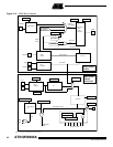
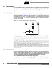
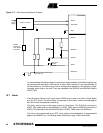
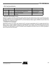
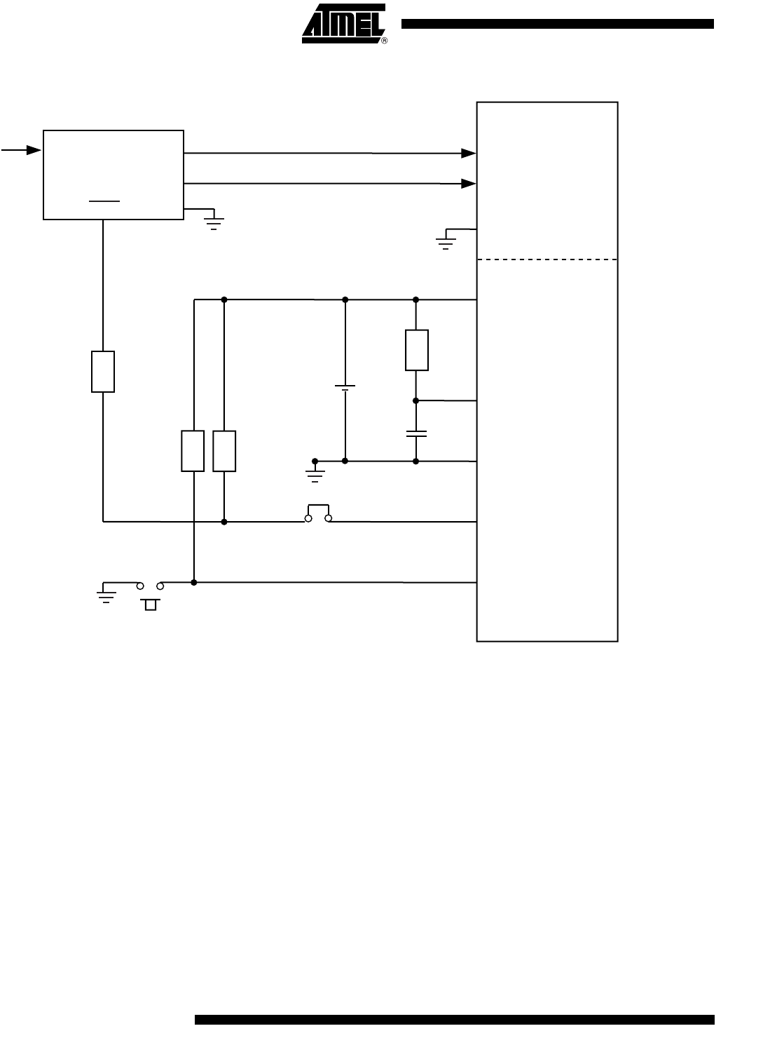
Figure 12-7. Shut-down and Wake-up Features
To accommodate the different types of main power supply available, and different signals that
can command the shut-down of this device, tri-state, level 0 and level 1 are user-definable for
the Shut-down pin. The Wake-up pin can be configured as detected on the positive or nega-
tive edge, and at high or low level. They are selected by the SHDALS and WKACKS fields in
APMC_PMR.
12.7 Alarm
If the Shut-down feature is not used, the pin SHDN can be used as an Alarm Output Signal
from the RTC Alarm. The Alarm State corresponds to Shut-down, and the Acknowledge or
Non-Alarm State corresponds to Wake-up.
The alarm control logic is the same as that for Shut-down. The SHDALC command in
APMC_PCR (defined by the field SHDALS in APMC_PMR) and the WKACKS command in
APMC_PCR (defined by the field WKACKS field in APMC_PMR) control the SHDN pin.
The alarm can be positioned by an RTC Alarm and be acknowledged by a programmable
edge on the WAKEUP pin. The Backup Reset initializes the logic in Non-Alarm State.
DC/DC ConverterPower
Supply
VDDIO
VDDCORE
GND
VDDBU
NRSTBU
GNDBU
SHDN
WAKE-UP
AT91M55800
SHD
Shut-down
Jumper
Disable
Main Start Up
Battery
Backup
-
+
Resistor
required by
some DC/DC
Converters