


27
1745D–ATARM–04-Nov-05
AT91M55800A
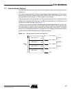
11.3 Data Bus Width
A data bus width of 8 or 16 bits can be selected for each chip select. This option is controlled
by the DBW field in the EBI_CSR (Chip-select Register) for the corresponding chip select.
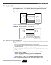
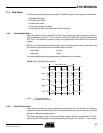
Figure 11-2 shows how to connect a 512K x 8-bit memory on NCS2.
Figure 11-2. Memory Connection for an 8-bit Data Bus
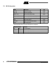
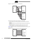
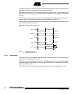
Figure 11-3 shows how to connect a 512K x 16-bit memory on NCS2.
Figure 11-3. Memory Connection for a 16-bit Data Bus
11.4 Byte-write or Byte-select Access
Each chip select with a 16-bit data bus can operate with one of two different types of write
access:
• Byte-write Access supports two Byte-write and a single read signal.
• Byte-select Access selects upper and/or lower byte with two byte-select lines, and separate
read and write signals.
This option is controlled by the BAT field in the EBI_CSR (Chip-select Register) for the corre-
sponding chip select.
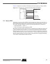
Byte-write Access is used to connect 2 x 8-bit devices as a 16-bit memory page.
• The signal A0/NLB is not used.
• The signal NWR1/NUB is used as NWR1 and enables upper byte writes.
• The signal NWR0/NWE is used as NWR0 and enables lower byte writes.
• The signal NRD/NOE is used as NRD and enables half-word and byte reads.
Figure 11-4 shows how to connect two 512K x 8-bit devices in parallel on NCS2.
EBI
D0 - D7
D8 - D15
A1 - A18
A0
NWR0
NRD
NCS2
D0 - D7
A1 - A18
A0
Write Enable
Output Enable
Memory Enable
NWR1
EBI
D0 - D7
D8 - D15
A1 - A19
NLB
NWE
NOE
NCS2
D0 - D7
D8 - D15
A0 - A18
Low Byte Enable
Write Enable
Output Enable
Memory Enable
NUB High Byte Enable