


185
1745D–ATARM–04-Nov-05
AT91M55800A
20. SPI: Serial Peripheral Interface
The AT91M55800A includes an SPI which provides communication with external devices in
master or slave mode.
The SPI has four external chip selects which can be connected to up to 15 devices. The data
length is programmable, from 8- to 16-bit.
As for the USART, a 2-channel PDC can be used to move data between memory and the SPI
without CPU intervention.
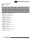
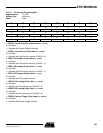
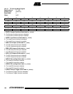
20.1 Pin Description
Seven pins are associated with the SPI Interface. When not needed for the SPI function, each
of these pins can be configured as a PIO.
Support for an external master is provided by the PIO Controller Multi-driver option. To config-
ure an SPI pin as open-drain to support external drivers, set the corresponding bits in the
PIO_MDSR register (see ).
An input filter can be enabled on the SPI input pins by setting the corresponding bits in the
PIO_IFSR.
The NPCS0/NSS pin can function as a peripheral chip select output or slave select input.
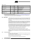
Refer to Table 1 for a description of the SPI pins.
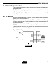
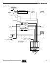
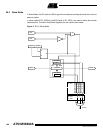
Figure 2. SPI Block Diagram
Serial Peripheral Interface
APB
MCK
MCK/32
Parallel IO
Controller
MISO
MOSI
SPCK
NPCS0/NSS
NPCS1
NPCS2
NPCS3
MISO
MOSI
SPCK
NPCS0/NSS
NPCS1
NPCS2
NPCS3
INT
Advanced
Interrupt Controller