


15
1745D–ATARM–04-Nov-05
AT91M55800A
In order to benefit the most regarding the separation of NRST and NTRST during the Debug
phase of development, the user must independently manage both signals as shown in exam-
ple (1) of Figure 7-1 above. However, once Debug is completed, both signals are easily
managed together during production as shown in example (2) of Figure 7-1 above.
7.4.3 Watchdog Reset
The watchdog can be programmed to generate an internal reset. In this case, the reset has
the same effect as the NRST pin assertion, but the pins BMS and NTRI are not sampled. Boot
Mode and Tri-state Mode are not updated. If the NRST pin is asserted and the watchdog trig-
gers the internal reset, the NRST pin has priority.
7.5 Emulation Functions
7.5.1 Tri-state Mode
The AT91M55800A provides a Tri-state Mode, which is used for debug purposes. This
enables the connection of an emulator probe to an application board without having to desol-
der the device from the target board. In Tri-state Mode, all the output pin drivers of the
AT91M55800A microcontroller are disabled.
To enter Tri-state Mode, the pin NTRI must be held low during the last 10 clock cycles before
the rising edge of NRST. For normal operation the pin NTRI must be held high during reset, by
a resistor of up to 400K Ohm.
NTRI is multiplexed with I/O line PA18 and USART 1 serial data transmit line TXD1.
Standard RS232 drivers generally contain internal 400K Ohm pull-up resistors. If TXD1 is con-
nected to a device not including this pull-up, the user must make sure that a high level is tied
on NTRI while NRST is asserted.
7.5.2 JTAG/ICE Debug Mode
ARM Standard Embedded In-Circuit Emulation is supported via the JTAG/ICE port. It is con-
nected to a host computer via an external ICE Interface. The JTAG/ICE debug mode is
enabled when JTAGSEL is low.
In ICE Debug Mode the ARM Core responds with a non-JTAG chip ID which identifies the core
to the ICE system. This is not JTAG compliant.
7.5.3 IEEE 1149.1 JTAG Boundary-scan
JTAG Boundary-scan is enabled when JTAGSEL is high. The functions SAMPLE, EXTEST
and BYPASS are implemented. There is no JTAG chip ID. The Special Function module pro-
vides a chip ID which is independent of JTAG.
It is not possible to switch directly between JTAG and ICE operations. A chip reset must be
performed (NRST and NTRST) after JTAGSEL is changed.
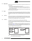
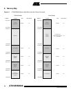
7.6 Memory Controller
The ARM7TDMI processor address space is 4G bytes. The memory controller decodes the
internal 32-bit address bus and defines three address spaces:
• Internal memories in the four lowest megabytes
• Middle space reserved for the external devices (memory or peripherals) controlled by the
EBI