


218
1745D–ATARM–04-Nov-05
AT91M55800A
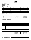
22. DAC: Digital-to-analog Converter
The AT91M55800A features two identical 1-channel 10-bit Digital-to-analog converters (DAC).
Each DAC has an analog output pin (DA0 and DA1) and provides an interrupt signal to the
AIC (DA0IRQ and DA1IRQ). Both DACs share the analog power supply pins VDDA and
GNDA, and the input reference pin DAVREF.
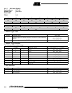
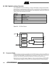
Figure 22-1. DAC Block Diagram
22.1 Conversion Details
Digital-to-analog conversions are possible only if the DAC has been enabled in the APMC and
the startup time has elapsed. This startup time is a maximum of 5 µsec, and is indicated more
precisely in the Electrical Characteristics datasheet of the device as parameter t
DASU
.
Digital inputs are converted to output voltages on a linear conversion between 0 and DAVREF.
The analog output voltages on DA0 and DA1 pins are determined by the following equation:
Table 22-1.
Pin Name Meaning
VDDA Analog power supply
GNDA Analog ground
DAVREF Reference voltage
DA0 Analog output, channel 0
DA1 Analog output, channel 1
+
-
Data Holding
Register
Data Output
Register
Control Logic
Trigger Selection
10-bit DAC
VDDA
GNDA
DAn
DAVREF
DAnIRQ
Advanced
Peripheral
Bus
TIOA0....TIOA5