


140
1745D–ATARM–04-Nov-05
AT91M55800A
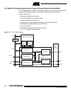
18.7 Peripheral Data Controller
Each USART channel is closely connected to a corresponding Peripheral Data Controller
channel. One is dedicated to the receiver. The other is dedicated to the transmitter.
Note: The PDC is disabled if 9-bit character length is selected (MODE9 = 1) in US_MR.
The PDC channel is programmed using US_TPR (Transmit Pointer) and US_TCR (Transmit
Counter) for the transmitter and US_RPR (Receive Pointer) and US_RCR (Receive Counter)
for the receiver. The status of the PDC is given in US_CSR by the ENDTX bit for the transmit-
ter and by the ENDRX bit for the receiver.
The pointer registers (US_TPR and US_RPR) are used to store the address of the transmit or
receive buffers. The counter registers (US_TCR and US_RCR) are used to store the size of
these buffers.
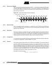
The receiver data transfer is triggered by the RXRDY bit and the transmitter data transfer is
triggered by TXRDY. When a transfer is performed, the counter is decremented and the
pointer is incremented. When the counter reaches 0, the status bit is set (ENDRX for the
receiver, ENDTX for the transmitter in US_CSR) and can be programmed to generate an inter-
rupt. Transfers are then disabled until a new non-zero counter value is programmed.
18.8 Interrupt Generation
Each status bit in US_CSR has a corresponding bit in US_IER (Interrupt Enable) and US_IDR
(Interrupt Disable) which controls the generation of interrupts by asserting the USART inter-
rupt line connected to the Advanced Interrupt Controller. US_IMR (Interrupt Mask Register)
indicates the status of the corresponding bits.
When a bit is set in US_CSR and the same bit is set in US_IMR, the interrupt line is asserted.
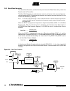
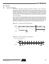
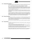
18.9 Channel Modes
The USART can be programmed to operate in three different test modes, using the field
CHMODE in US_MR.
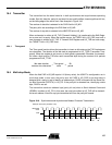
Automatic echo mode allows bit by bit re-transmission. When a bit is received on the RXD line,
it is sent to the TXD line. Programming the transmitter has no effect.
Local loopback mode allows the transmitted characters to be received. TXD and RXD pins are
not used and the output of the transmitter is internally connected to the input of the receiver.
The RXD pin level has no effect and the TXD pin is held high, as in idle state.
Remote loopback mode directly connects the RXD pin to the TXD pin. The Transmitter and
the Receiver are disabled and have no effect. This mode allows bit by bit re-transmission.