


159
1745D–ATARM–04-Nov-05
AT91M55800A
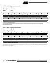
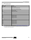
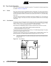
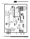
19.1 Signal Name Description
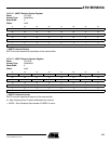
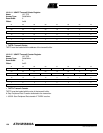
Notes: 1. After a hardware reset, the TC clock is disabled by default ( See “APMC: Advanced Power Management Controller” on page
52.). The user must configure the Power Management Controller before any access to the User Interface of the TC.
2. After a hardware reset, the Timer Counter block pins are controlled by the PIO Controller. They must be configured to be
controlled by the peripheral before being used.
Table 19-1. Signal Name Description
Channel Signals Description
XC0, XC1, XC2 External Clock Inputs
TIOA
Capture Mode: General-purpose input
Waveform Mode: General-purpose output
TIOB
Capture Mode: General-purpose input
Waveform Mode: General-purpose input/output
INT Interrupt signal output
SYNC Synchronization input signal
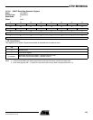
Block 0 Signals Description
TCLK0, TCLK1, TCLK2 External Clock Inputs for Channels 0, 1, 2
TIOA0 TIOA signal for Channel 0
TIOB0 TIOB signal for Channel 0
TIOA1 TIOA signal for Channel 1
TIOB1 TIOB signal for Channel 1
TIOA2 TIOA signal for Channel 2
TIOB2 TIOB signal for Channel 2
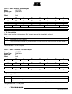
Block 1 Signals Description
TCLK3, TCLK4, TCLK5 External Clock Inputs for Channels 3, 4, 5
TIOA3 TIOA signal for Channel 3
TIOB3 TIOB signal for Channel 3
TIOA4 TIOA signal for Channel 4
TIOB4 TIOB signal for Channel 4
TIOA5 TIOA signal for Channel 5
TIOB5 TIOB signal for Channel 5