


207
1745D–ATARM–04-Nov-05
AT91M55800A
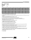
21. ADC: Analog-to-digital Converter
The AT91M55800A features two identical 4-channel 10-bit Analog-to-digital converters (ADC)
based on a Successive Approximation Register (SAR) approach.
Each ADC has 4 analog input pins (AD0 to AD3 and AD4 to AD7), digital trigger input pins
(AD0TRIG and AD1TRIG), and provides an interrupt signal to the AIC. Both ADCs share the
analog power supply pins (VDDA and GNDA) and the input reference voltage pin (ADVREF).
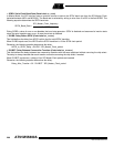
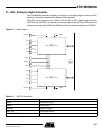
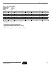
Figure 21-1. Block Diagram
Table 21-1. ADC Pin Description
Pin Name Description
VDDA Analog power supply
GNDA Analog ground
ADVREF Reference voltage
AD0 - AD7 Analog input channels
AD0TRIG, AD1TRIG External triggers
ADIRQ0
ADIRQ1
ADC 1
Analog-to-digital Converter
ADC 0
Analog-to-digital Converter
APB
Advanced
Peripheral
Bus
AD0TRIG
AD0
AD1
AD2
AD3
VDDA
ADVREF
GNDA
AD4
AD5
AD6
AD7
AD1TRIG