


CIRCUIT DESCRIPTION
6-22
March 1999
Part No. 001-2009-600
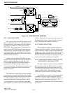
WO 122 RF OUT 1
This capacitive feedthrough pin is a voltage
source that is a function of the output power of Q701.
The voltage level will be between 0V-5V and drive a
10k ohm load. This line goes through the multiplexers
and A D LEVEL line to the Controller for processing.
WO 123 RF OUT 2
This capacitive feedthrough pin is a voltage
source that is a function of the output power of Q702.
The voltage level will be between 0V-5V and drive a
10k ohm load. This line goes through the multiplexers
and A D LEVEL line to the Controller for processing.
WO 124 RF OUT 3
This capacitive feedthrough pin is a voltage
source that is a function of the output power of Q703.
The voltage level will be between 0V-5V and drive a
10k ohm load. This line goes through the multiplexers
and A D LEVEL line to the Controller for processing.
WO 125 RF OUT 4
This capacitive feedthrough pin is a voltage
source that is a function of the output power of Q704.
The voltage level will be between 0V-5V and drive a
10k ohm load. This line goes through the multiplexers
and A D LEVEL line to the Controller for processing.
WO 126 REFL PWR
This capacitive feedthrough pin is the reflected
power sense line. It is a voltage indicative of the
power reflected due to a mismatch. The voltage pro-
duced will typically be such that less than a 3:1
VSWR will not trigger alarms and when VSWR = 6:1
the controller will reduce power. The voltage level
will be between 0V-5V and drive a 10k ohm load.
This line goes through the multiplexers and A D
LEVEL line to the Controller for processing. The
time to sense and reduce the power takes several sec-
onds.
WO 127 TEMP
This capacitive feedthrough pin is the tempera-
ture sense line of the Power Amplifier. It will be a lin-
early variable function of temperature ranging from
0V-5V output and 0°C to +100°C (+32°F to 212°F)
input when driving a 10k ohm load. The primary
functions of this line are for fan on/off and PA power
reduction. The fan should be turned on at 50°C and
off at 45°C. The PA should have power reduced when
90°C (194°F) is reached and with absolute turn-off at
95°C (203°F). This line goes through the multiplexers
and A D LEVEL line to the Controller for processing.
WO147 RF DETECT PRE-DRIVER
This senses power out of the pre-driver. It is used
to limit the power out of the pre-driver to
0.6 dB over 160W at room temperature. The 75W
repeater limits to 0.6 dB over 75W.
W143 +26V DC
This is the +26.5V DC source to the RFIB from
P101.
W144 +15V DC
This is the +15V DC source to the RFIB from
P103.
W145 GROUND
W145 carries ground current from P104 to the
RFIB.
6.6.5 EXCITER CONNECTOR (J102)
The connector from the Exciter (J401) to the RF
Interface board (J102) links the Exciter to the MPC in
the Controller Backplane.
Pin 1 VCC1
The voltage on this pin is a fused +15V ±1%,
nominal current of 0.5A. It provides current to the
Exciter from the RFIB.
Pins 2-8 GROUND
Pin 9 +3.5V DC
Pin 9 is the +3.5V DC TCXO reference voltage
from the Exciter to the MAC.