


ALIGNMENT AND TEST PROCEDURES
7-6
March 1999
Part No. 001-2009-600
NOTE: If the Transmit current begins to increase rap-
idly and is not constant with time, then unkey the PA
immediately and troubleshoot.
3. Adjust power limit control R76 clockwise until
power is limited to 0.55 dB above 85W (95W). If
the maximum PA power is < 95W, adjust R76 until
power begins to decrease.
7.4.4 REFLECTED POWER ADJUST
1. Remove the load cable from A8.
2. Use the "Turn on carrier" button to key the PA.
NOTE: This will not harm the PA.
3. Adjust Reverse Power Calibration Pot R680 for
equal voltages on W126 and W121 on the RFIB or
for equal Forward and Reverse Power.
4. Use the "Turn on carrier" button to unkey the PA.
5. Apply "Glyptol" to R663, R680 and R76.
6. Use the “Turn fan on” button to turn on/off fans.
Both PA fans should turn ON.
7. Measure temperature detector voltage at W127 on
the RFIB. Normal output at 25°C ambient is
approximately +1.0V DC.
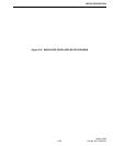
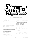
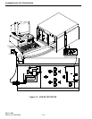
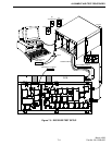
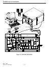
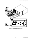
Figure 7-3 POWER AMPLIFIER ALIGNMENT POINTS
R680
R663
A8
R509
Q503
Q502
B
Q501
U501
C537
R508