


INSTALLATION
2-6
March 1999
Part No. 001-2009-600
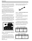
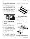
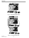
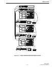
2.9 REPEATER DATA BUS INSTALLATION
The repeaters are interconnected by a balanced
line High-Speed Data Bus (HSDB) consisting of a six
conductor cable. The total length of the HSDB cannot
exceed 500 feet. Connect the cables in daisy-chain
fashion to modular connector A5 on the back of the
repeater (see Figure 2-16). A 50 ohm termination is
not required for VIKING VX repeaters.
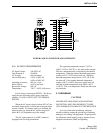
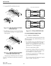
2.9.1 MPC DATA BUS SWITCH SETTINGS
Switch settings on the MPC for the two types of
installations require S2 and S3 sections to be switched
as indicated in Figure 2-5.
Figure 2-5 MPC DATA BUS SWITCHES
123
4
1
234567
8
ONLY VIKING VX REPEATERS
ONLY VIKING VX END REPEATERS
(CENTER REPEATERS)
ON
ON
2
1
87
6
5
4
3
2
1
4
3
S3 S2
ON
2
1
4
3
S3
ON
2
1
8
7
6
5
4
3
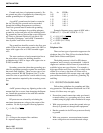
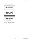
2.9.2 MPC DATA BUS JUMPER SETTINGS
Refer to Figure 2-6 for crystal selection and
HSDB Code selections jumper placement. Jumper
J5, pins 1-2 selects 11.059 MHz for LTR-Net (J5, pins
2-3 selects 12 MHz crystal for Standard LTR). The
jumper on J4, pins 5-6 connects EPROM U14, pin 27
to ground for LTR-Net (J4, pins 3-4 connects EPROM
U14, pin 27 (A14) to +5V for Standard LTR single-
ended 5V data bus).
Figure 2-6 MPC JUMPERS
Jumper J4 must be placed with the following
guidelines: J4, pins 5-6 for operation with the RJ-11 to
RJ-11 cable 200X systems (see Section 4.5.6).
23
1
J5
J4
1
2
3
46
5
HSDB CODE SELECTION
CRYSTAL SELECTION
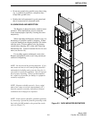
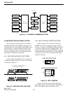
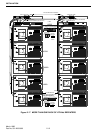
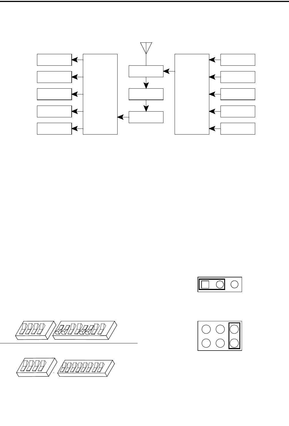
Figure 2-4 5-CHANNEL COMBINING SYSTEM
RECEIVER 1
RECEIVER 2
RECEIVER 3
RECEIVER 4
RECEIVER 5
RECEIVER
MULTICOUPLER
PREAMPLIFIER
FILTER
DUPLEXER
TRANSMITTER
COMBINER
TRANSMITTER 1
TRANSMITTER 2
TRANSMITTER 3
TRANSMITTER 4
TRANSMITTER 5
T/R ANTENNA
BANDPASS