


ALIGNMENT AND TEST PROCEDURES
7-7
March 1999
Part No. 001-2009-600
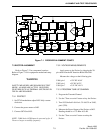
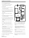
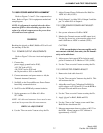
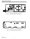
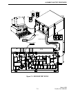
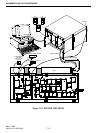
7.5 160W POWER AMPLIFIER ALIGNMENT
Refer to Figures 7-4 and 7-5 for component loca-
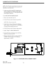
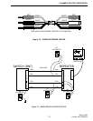
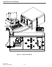
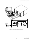
tions. Refer to Figure 7-8 for equipment needed and
setup diagram.
NOTE: No alignment is required unless the driver
transistor Q502 or driver matching caps have been
replaced or critical components on the power detec-
tor board have been replaced.
WARNING
Breaking the glyptol on R663, R680 or R76 will void
the warranty on the PA.
7.5.1 POWER OUTPUT ADJUSTMENTS
Refer to Figure 7-8 for test circuit and equipment
needed.
1. Connect the:
power supply ground lead to P105,
+15V DC lead to P103,
+26.5V DC lead to P101 and
the 36-pin cable to J101 on the RFIB.
2. Connect attenuator and power meter to A8, the
Transmit Antenna Connector.
3. Set R663 on the Forward/Reverse Power Detect
board fully counterclockwise.
4. Set R76 on the RFIB fully counterclockwise.
5. Set the generator to +15 dBm ±0.1 dB at
937.5 MHz.
NOTE: All cable and attenuator losses must be mea-
sured and incorporated into this measurement.
CRITICAL ADJUSTMENT
6. Use the "Turn on carrier" button to key the PA.
7. Adjust Forward Power Calibration Pot R663 for
160W ±0.1 dB (±3.5W).
8. Verify Output 1 is within 20% of Output 2 and Out-
put 3 is within 20% of Output 4.
7.5.2 PRE-DRIVER POWER LIMIT ADJUST-
MENT
1. Set a power reference of 0 dB at 160W.
2. Monitor the Transmit current and RF output level.
Use the Up Arrow key to increase the power level
until 0.8 dB above 160W is reached (192W).
CAUTION
If TX current begins to increase rapidly and is
not constant with time, then unkey the PA immedi-
ately and troubleshoot.
3. Adjust power limit control R76 clockwise until
power is limited to 0.75 dB above 175W (192W).
4. Use the "Turn on carrier" button to unkey the PA.
7.5.3 REFLECTED POWER ADJUST
1. Remove the load cable from A8.
2. Use the "Turn on carrier" button to key the PA. This
will not harm the PA.
3. Adjust Reverse Power Calibration Pot R680 for
equal voltages on W126 and W121 on the RFIB or
for equal Forward and Reverse Power.
4. Use the "Turn on carrier" button to unkey the PA.
5. Apply ’glyptol’ to R663, R680 and R76.
6. Use the “Turn on fan” button to turn on/off fans.
Both PA fans should turn ON.
7. Measure temperature detector voltage at W127 on
the RFIB. Normal output at 25°C ambient is
approximately +1V DC.