


CIRCUIT DESCRIPTION
6-38
March 1999
Part No. 001-2009-600
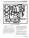
6.12 MAIN AUDIO CARD
6.12.1 INTRODUCTION
This control card stores the information required
to operate the routing of audio and data from the
inputs of the repeater to the outputs. Data is received
on the address bus from the MPC for the operations to
perform. The Audio/Data microprocessor and the
latches open and close gates to route a path for the
audio or data.
Audio control functions for each repeater are per-
formed by the main processor in the MPC. The MPC
contains the software and maintains control over the
repeater via microprocessor U27. The audio/data
microprocessor passes received data to the main pro-
cessor, and it is given the programmable parameters
for the gates.
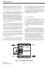
Information is exchanged between the cards in
the Controller Backplane via a data bus and an address
bus. The address bus provides the link between the
main processor and the chip and the address latches on
the MAC. These latches control the octal latches that
select the audio and data gates. The data bus is the
link between the main processor and the audio/data
processor on the MAC. The main processor controls
the data to the octal latches and opens and closes the
gates required to route audio/data in and out of the
repeater. The MAC also contains:
• The audio interface between the receiver and exciter
and to the external connections.
• The receive audio filtering with de-emphasis.
• The squelch filter and detector.
• Slow decay timing circuit that controls a mute gate
on the main receive audio.
• A filter, DC restoration and slicer circuitry for
detecting the subaudible data.
• The fast squelch and data fed to the microprocessor
that decodes the data and uses the squelch line as a
data qualification signal.
• Transmit audio filter and limiter with pre-emphasis.
6.12.2 AUDIO/DATA MICROPROCESSOR
This Audio/Data microprocessor is on the MAC
card and is used to decode LTR data received from the
mobiles. The LTR data is applied to U111, pin 8 (P1.7
input). When a word is successfully decoded the data
is then sent to U161 (Tx FIFO) and transmitted on the
data bus in parallel to the main processor on the MPC.
When it is time to transmit the CW Identification,
the main processor on the MPC sends the identifica-
tion to U111 via the data bus and U160 (Rx FIFO).
The CWID is sent to the Tx Data Amplifier and Fil-
ter. The output of the filter is summed with the trans-
mit audio and sent to the Exciter.
U111 also uses six octal latches to provide addi-
tional input and output lines. Latch U107/U108 pro-
vide outputs which allow U111 to control various
audio gates. These gates control the CWID, FSK data,
and receive/transmit audio signals.
Latch U106 provides outputs which allow U111
to route signals to the Audio/Data Test Point by
switching gates on and off. U106 also provides adjust-
ment of the selected EEPOTs.
U155-U156 allow U111 to select the EEPOT to
adjust with chip select lines. These latches also pro-
vide routing of some audio/data signals through gates.
U111 also decodes data from the Switch and
transmits data to the Switch. In addition, it controls
the FSK modem (U110), receive and transmit audio
gates, receiver squelch, several front-panel indicators,
and other functions.
U111 encodes the data messages transmitted to
mobiles monitoring that channel, and controls trans-
mitter keying. The MAC also contains circuitry which
provides amplification and filtering of the receive and
transmit audio and data signals. In addition, a modem
integrated circuit (U110) provides FSK encoding and
decoding of data transmitted and received from the
Switch.
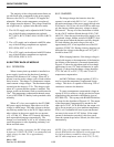
6.12.3 RECEIVE AUDIO
The Receive Wide Band Audio (RX WBAND)
signal from the Receiver is fed into the MAC on P100,
pin 27. This audio signal includes; audio, LTR-Net