


SERVICING
8-5
March 1999
Part No. 001-2009-600
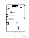
Standby Battery Jack
This provides a connection point for a +24V DC
standby battery. Current is drawn from the battery
only when the repeater enable line is on and AC has
failed, or no AC is connected. A trickle charger can
be jumpered in to charge the battery when AC returns.
The charger jumper is removed when a separate bat-
tery charger is used (see Figure 8-4). The standby bat-
tery connection to the power supply must be ordered
installed from the factory.
NOTE: A small amount (<30 mA) of current is drawn
from the batteries with the repeater off. If the repeater
is going to be turned off for more than one week (with
good batteries connected) the fuse should be removed
from the DC cable harness.
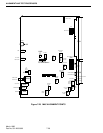
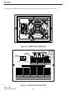
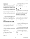
8.5.1 VOLTAGE CHECKS
Secondary voltages can be checked at the power
supply connector with the power supply removed
from the Repeater. First the on/off line must be
grounded, jumper pin 5 to ground, then check the sup-
ply voltages as shown (see Figure 8-2). If voltages are
absent the supply must be sent to the E.F. Johnson
Company.
8.6 CHIP COMPONENT IDENTIFICATION
8.6.1 CERAMIC CHIP CAPS (510-36XX-XXX)
Ceramic chip capacitors are identified using
either an American or Japanese EIA standard. The
values for both standards are shown in Table 8-2.
American EIA Standard
This uses a single letter or number to indicate the
value, and the color of this letter or number to indicate
the multiplier.
Japanese EIA Standard
This uses a letter to indicate the value followed
by a number to indicate the multiplier.
Example: 15 pF capacitor
American - Single Black "E"
Japanese -"E1"
The Japanese EIA Standard may also utilize a bar
to indicate the temperature coefficient.
Example: A2
- 100 pF NPO
XX = NPO X
X = N150 XX = N220
XX
= N330 XX = N470 XX = N750
|XX = X7R
8.6.2 TANTALUM CHIP CAPS (510-26XX-XXX)
Tantalum chip capacitor identification varies with
vendor and physical size. The positive (+) end is usu-
ally indicated by a colored board or beveled edge.
The value and voltage may be indicated by printing on
the capacitor or by using a special code.
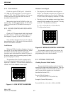
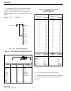
8.6.3 CHIP INDUCTORS (542-9000-XXX)
Three colored dots are used to indicate the value
of chip inductors. The two dots on the left side indi-
cate the first and second digits of the value in nano-
Henries, and the single dot on the right side indicates
the multiplier (see Table 8-1).
Example: Dots - Brown-Black-Red
10 nH x 100 = 1000 nH (1.0 µH)
The last three digits of the part number are also
the value and multiplier. The multiplier digits are
shown in Table 8-1.
8.6.4 CHIP RESISTORS
The value of chip resistors is indicated by a num-
ber printed on the resistor. A 3-digit number is used to
identify ±5% and ±10% resistors, and a 4-digit num-
ber is used to identify ±1% resistors.
The 3-digit number used to identify ±5% and
±10% resistors corresponds to the last 3-digits of the
E.F. Johnson part number. This number is derived as
shown.
Example:
273 27k ohm
339 3.3 ohm