


6-1
March 1999
Part No. 001-2009-600
SECTION 6 CIRCUIT DESCRIPTION
6.1 RECEIVER
6.1.1 INTRODUCTION
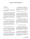
The receiver provides high sensitivity and selec-
tivity reception on any one of the 399 channels in the
896 to 901 MHz band.
The receiver is a double conversion type with
intermediate frequencies of 52.95 MHz and 450 kHz.
The first injection frequency is stabilized by a temper-
ature compensated crystal oscillator (TCXO) with a
frequency stability of ±0.1 PPM from -30°C to +60°C
(-22°F to +140° F). Two 3-pole bandpass filters in the
front-end reject signals outside the receive band. Two
4-pole crystal filters and one 6-pole ceramic filter
establish receiver selectivity (see block diagram
Figure 6-1).
6.1.2 REGULATED VOLTAGE SUPPLIES
The +15V DC power source is supplied by the
repeater power supply. The +15V supply enters the
receiver on J201, pin 1. U206 provides the +12V DC
receive voltage to the RF and IF amplifiers. U210
supplies +12V DC to the first injection amplifiers.
U207 supplies +12V DC to remaining +12V DC cir-
cuits. U208 supplies +6V DC to the remaining
circuits.
6.1.3 HELICAL FILTER, RF AMPLIFIER
The receive signal enters the receiver on coaxial
connector A201. A helical filter consisting of L201,
L202 and L203 is a three-pole bandpass filter tuned to
pass only a narrow band of frequencies (896-901
MHz) to the receiver. This filter also attenuates the
image and other unwanted frequencies.
Impedance matching between the helical filter
and RF amplifier Q201 is provided by C201, C202 and
a section of microstrip. Q201 amplifies the receive
signal to recover filter losses and increases receiver
sensitivity. Biasing for Q201 is provided by R201/
R202/R203/R204 and C204 provides RF bypass.
A 1.8 dB attenuator follows amplifier Q201.
Additional filtering of the receive signal is provided by
3-pole helical filter L204-L206. A section of micros-
trip on the collector of Q201 and C205/C207 match
the impedance from Q201 to the 3-pole helical filter
L204-L206.
6.1.4 FIRST MIXER, CRYSTAL FILTER
First mixer U201 mixes the receive frequency
with the first injection frequency to produce the 52.95
MHz first IF. Since low-side injection is used, the
injection frequency is 52.95 MHz below the receive
frequency. Matching between filter L204-L206 and
the mixer is provided by L228, C208 and C372. The
output of U201 is matched to Z201 at 52.95 MHz by
L207, C209 and C267.
Z201 and Z202 form a two-section, four-pole fil-
ter with a center frequency of 52.95 MHz and a -3 dB
bandwidth of 8 kHz. This filter attenuates adjacent
channels and other signals close to the receive fre-
quency. The filter sections are a matched pair and the
dot on the case indicates which leads connect together.
Matching with Q202 is provided by C210, L209 and
C270.
6.1.5 IF AMPLIFIER, CRYSTAL FILTER
Q202 amplifies the 52.95 MHz IF signal to
recover filter and mixer losses and improve receiver
sensitivity. Biasing for Q202 is provided by R208/
R209/R211/R313 and C211/C212/C213 provide RF
bypass. The output of Q202 is matched to crystal fil-
ter Z203 at 52.95 MHz by C214, C293 and L211.
Z203 and Z204 form a two-section, four-pole fil-
ter with a center frequency of 52.95 MHz and a -3 dB
bandwidth of 8 kHz. This filter establishes the selec-
tivity of the receiver by further filtering the 52.95
MHz IF. The filter sections are a matched pair and the
dot on the case indicates which leads connect together.
Matching with U202 is provided by C215, C216,
C301, L225 and R322.