


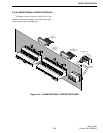

CIRCUIT DESCRIPTION
6-41
March 1999
Part No. 001-2009-600
Limiter U127D and rectifiers form a precision
limiter which prevents over modulation caused by
high-level input signals. With normal input levels, the
output of a bridge rectifier follows the input of the
bridge. When a high-level signal is applied to the
bridge, the bridge opens and the output of the bridge is
limited to a specific level.
The output of the limiter passes to a composite 6-
pole splatter filter formed by U127A, U128D and
U128A separated by buffers U128B and U128C.
The output from U128A is fed to Normal Modu-
lation Mute Gate U118B. This gate is controlled by
A/D processor U111/latch U106. When enabled, the
gate passes transmit audio to EEPOT U149. U149 is
an electronically adjustable potentiometer that adjusts
the gain of transmit audio amplifier U129C. The gain
of U129C can only be adjusted through the software.
Therefore, a computer must be attached to the MAC
card when levels are set.
The output of U129C is fed to summing amplifier
U129B where it is combined with Multi-Net transmit
data and CWID when present. The gain of audio and
data are the same so unity gain is produced. The out-
put signal is fed to the TCXO where it frequency mod-
ulates the transmit signal.
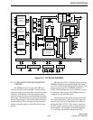
6.12.10 TRANSMIT AUDIO PROCESSING
This is not a Simulcast operation. The balanced
audio signal from the Switch is applied to U167A.
This stage is a differential amplifier which converts
the input signal to a single-ended output. The input
impedance is set at 600 ohms. The output signal is
applied to Transmit Audio amplifier U167B. The gain
of U167B is adjusted by a level control. The output of
the amplifier is connected to two gates. One is the
Transmit Audio To FSK U116D. This gate is con-
trolled by A/D processor U111/latch U107. When
enabled, this gate passes the FSK blank and burst data
from the Switch to the Secondary Audio from the
Switch converter U131C.
When data and audio share the same path,
U131D amplifies the signal and applies it to two gates.
When enabled Transmit Secondary To FSK gate
U153D passes the audio to FSK Modem U110. The
other gate is Data Level Test Gate U133A. When
enabled U153A passes the signal to Transmit Option
Gate U158C and Level Detect Gate U159A to Audio/
Data Test Point J100. The other gate is the Transmit
Audio Gate U116C. This gate is also controlled by A/
D processor U111/latch U107. When audio from the
Switch is to be transmitted, Transmit Audio Gate
U116C is enabled and passes the signal and Repeat
Gate U153C is disabled interrupting the receive audio
signal. When enabled, this gate passes the Main
Audio from the Switch to Transmit Option Gate
U158C and on to the transmit audio buffer U164B.
Transmit voice from the backplane comes into
the MAC on P100, pin 32. When used, this signal
passes to the transmit voice amplifier U130A. The
amplifier output level is adjusted by a level control.
The output of U130A is applied to another transmit
voice amplifier U130B and Transmit Voice Gate
U158A. U158A is controlled by A/D processor U111/
latch U107. When enabled, the gate passes the voice
to Transmit Option Gate U158C and on to the transmit
audio buffer U164B. Transmit Voice amplifier U130B
is adjusted by a level control. The output is fed to
Transmit Net Gate U153B. Gate U153B is controlled
by A/D processor U111/latch U155. When enabled,
this gate passes transmit voice to FSK Modem U110.
6.12.11 TRANSMIT DATA AND CWID PROCESS-
ING
This is not a Simulcast operation. The data sig-
nal is produced by A/D processor U111 on Transmit
Data and Transmit Shape outputs. The transmit shape
output is normally the opposite logic level of the
transmit data output when data is transmitted. How-
ever, the bit before a logic transition occurs, the trans-
mit shape output is the same logic level as the transmit
data output. This results in a slightly higher logic 1
level and a logic 0 that is slightly lower. This pulse
shaping minimizes interference between data bits
when the data is filtered by the low-pass filter.
The data from U111 is fed to buffer U126A and
Transmit Data Enable Gate U117B. Gate U117B is
controlled by A/D processor U111 directly. When
enabled this gate passes the data to EEPOT U151.
U151 is an electronically adjustable potentiometer that
adjusts the gain of transmit audio amplifier U126B.
The gain of U126B can only be adjusted through the
software. Therefore, a computer must be attached to
the MAC card. U126B provides the required signal
level at the output of the low-pass filter. A relatively