


INTRODUCTION AND OPERATION
1-10
March 1999
Part No. 001-2009-600
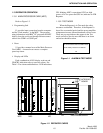
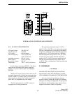
1.14.4 SWITCH
The Switch can connect several different forms of
communication together to form a communication net-
work that requires the Call Processor. It has up to six
shelves with 12 or 16 device slots each (72 or 96 slots
available) and up to three racks (for 216 or 288 slots).
Many different modules are available to complete the
network. Some modules have specific device slot
requirements.
1.14.5 CALL PROCESSOR AND SYSTEM AND
SUBSCRIBER MANAGER
The Call Processor, along with the System and
Subscriber Manager, controls the LTR-Net System.
The Call Processor (CP) is an IBM
PC or compatible
computer that is running the EFJohnson management
program. The System and Subscriber Manager soft-
ware is used by the System Administrator to program,
control and continuously monitor Switch operation,
and provides logging of information for billing pur-
poses.
The System and Subscriber Manager (SSM) is a
program that executes on an IBM PC or compatible
computer. The function of the SSM is to manage the
database information that the Call Processor uses in its
operation. The SSM has the capability to generate
reports from the logged information of the CP. The
SSM also has the ability to setup and initiate such
activities as Dynamic Reprogramming of certain
mobile parameters (Group 11), disabling (Kill) of lost
or stolen mobiles and many other functions.
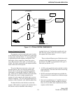
1.14.6 LOCALITY
A Locality is the location where one or more
repeaters are housed. Trunked system repeaters are
connected to the same high-speed data bus and are
required to be located close together. LTR-Net can
have a maximum of 20 repeaters at a Locality. One
CIM (Channel Interface Module) is required for each
LTR-Net repeater. A CCM (Conventional Channel
Module) is required for a conventional channel.
1.14.7 HOME REPEATER CHANNEL
All LTR-Net mobiles have one of the Locality
repeaters assigned as their "Home Repeater". This
repeater handles the data and audio unless a failure
causes the Status Repeater to take over. The Group ID
calls use the Home Repeater number in identifying the
mobiles (see Section 1.15.3).
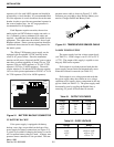
1.14.8 STATUS REPEATER CHANNEL
The Status Repeater Channel is one repeater at a
Locality designated to transmit update information for
all calls occurring at that Locality. The Status repeater
is a "Home Repeater" backup usually not assigned
voice traffic.
1.14.9 MONITOR REPEATER CHANNEL
This is the repeater channel that a mobile is cur-
rently monitoring for update messages. This repeater
may be either the mobile’s Home Repeater or the
Locality Status Repeater. A special algorithm is used
by the mobile to determine which is to be monitored.
Generally, it is the last repeater that a valid data mes-
sage was detected on.
1.14.10 HOME CHANNEL ALIASING
The LTR-Net Home Channel Aliasing feature
increases the number of addresses available on a
Locality for Group calls. It does this by allowing calls
to be programmed on non-exisent Home repeaters.
Each Home repeater can be programmed with 1-
239 Group ID codes. Assume a Locality has four
active repeaters and one of these is the Status repeater
(that is normally not assigned as a Home repeater).
The number of calls that can be programmed are then
as follows:
Without Aliasing - 3 x 239 or 717 calls
With Aliasing - 20 x 239 or 4780 calls
When a call is placed on a non-existent Home
repeater, the subscriber unit automatically uses the
next lower numbered active repeater.
NOTE: Since this feature does not increase system
capacity, adding too many users may result in unsatis-
factory operation due to frequency busy conditions.