


INSTALLATION
2-4
March 1999
Part No. 001-2009-600
Ground each piece of equipment separately. Do
not ground one piece of equipment by connecting it to
another grounded piece of equipment.
A good DC ground must be found or created at
the site. Rooftop site grounds can be researched
through the building management or architects.
Tower site grounds must be made with grounding
rods. The many techniques for providing adequate
grounds for towers and poles and for installing build-
ing ground bus lines are beyond the scope of this man-
ual. Refer to National Electrical Code article 250
"Grounding Techniques," article 800 "Communica-
tions Systems" and follow local codes.
The ground bus should be routed to the floor area
within 5 feet of the system with a runner of 6 AWG or
larger solid copper wire or 8 AWG stranded copper
wire.
The outer conductor of each transmission line at
the point where it enters the building should be
grounded using 6 AWG or larger solid copper wire or
8 AWG stranded wire.
Secondary protection (other than grounding) pro-
vides the equipment protection against line transients
that result from lightning. There are two types of sec-
ondary protection, RF and Telephone Line. Use the
same wire sizes as specified for coaxial cables for any
ground connections required by the secondary protec-
tors.
RF
An RF protector keeps any lightning strike to the
antenna feed line or tower from damaging the Repeat-
ers. Install this protection in-line with the combiner
and antenna feed line.
RF protectors are selected by calculating the
maximum instantaneous voltage at the output of the
combiner. Do this by using the following equation.
V
P
= 1.414 (X) (√P(50))
Where:
V
P
= Voltage at the output of the combiner.
P = repeater output in watts
X= for VSWR=
1.05 1.10 : 1
1.09 1.20 : 1
1.13 1.30 : 1
1.17 1.40 : 1
1.20 1.50 : 1
1.30 1.86 : 1
Example: Repeater power output of 60W with a
VSWR of 1.3 : 1 (for this VSWR, X = 1.13):
V
P
= 1.414 (1.13) (√60(50))
V
P
= 1.59782 (√60(50))
V
P
= 1.59782 (54.772256)
V
P
= 87.52V
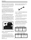
Telephone Line
There are four types of protection suppressors for
telephone lines; Gas Tube, Silicon Avalanche Diode,
Metal Oxide Varistor and Hybrid.
The hybrid protector is ideal for EF Johnson
equipment, and is strongly recommended. A hybrid
suppressor combines several forms of protection not
available in just one type of device. For example, a
high-speed diode reacts first clamping a voltage strike
within 10 ns, a heavy duty heat coil reacts next to
reduce the remainder of the current surge, and a high-
powered three-element gas tube fires, grounding Tip
and Ring.
2.7.1 PROTECTION GUIDELINES
Follow these guidelines for grounding and light-
ning protection. Each Repeater installation site is dif-
ferent; all of these may not apply.
• Ensure that ground connections make good metal-
to-metal contact (e.g. grounding rod or tray, metal
conduit) using #6 gauge solid or braided wire straps.
• With surge protectors, ensure that ground wires go
directly to ground, not through other equipment.
• Run the ground wire for RF coax protectors directly
to ground.
• With coax protectors, ensure maximum instanta-
neous voltage does not exceed the rated voltage.