


CIRCUIT DESCRIPTION
6-13
March 1999
Part No. 001-2009-600
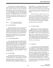
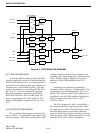
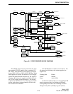
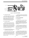
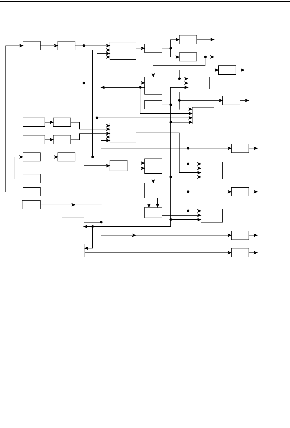
Figure 6-5 OCXO DRAWER BLOCK DIAGRAM
OCXO 1
OCXO 2
Q901Y901
Y902
BUFFER
BUFFER
Q902
DIVIDER
U905
LINE DRIVERS
U906A
U906B
SWITCH
REMOTE SWITCH
S904
OCXO SWITCH
S905
REMOTE SWITCH
S904
OCXO SWITCH
S905
CR902/CR903
U908
CR904/CR905
U909
SWITCH
U901A/C/D
U903D, U904A
U902B, U904D
U901A/B/C/D,
(OSC 1)
(OSC 2)
10 MHz REF OUT
1.25 MHz REF OUT
U907
ONE-SHOT
MULTIVIBRATOR
STROBE CLOCK
U904B/C/D
ONE-SHOT
MULTIVIBRATOR
U911
U910A
COMPARATOR
VCO/PHASE
U913
FLIP-FLOP
FLIP-FLOP
U910B
OCXO RF OUTPUT
ALARM INDICATOR
Q903, DS901
U902C, Q904
Q905, K901
ALARM RELAY
RF ALARM OUT
ALARM INDICATOR
ALARM RELAY
Q906, DS902
U903C, U912A
Q907
OCXO 1
Q908, K902 OCXO 1 ALARM
ALARM INDICATOR
ALARM RELAY
OCXO 2
Q909, DS903
U903A, U912B
Q910
Q911, K903 OCXO 2 ALARM
ALARM INDICATOR
ALARM RELAY
DELTA F
Q912, DS904
U914B, Q913
Q914, K904 DELTA F
ALARM RELAY
ALARM RELAY
Q918, Q919
Q920, K905
DC ALARM
Q923, Q924
Q920, K906
AC ALARM
DC ALARM
INDICATOR
U914A, Q916
Q917, DS905
S902
S903
SWITCH CONTROLS
FRONT PANEL
OCXO 1
S901
TEST
TEST
OCXO 2
DC ON/OFF
INDICATOR
AC ALARM
Q912, DS906
U914D, Q921
FAIL STROBE
The OCXO drawer may be powered by the inter-
nal regulated 15V DC supply, or by an external 15V
DC source. The internal 15V DC supply is powered
from a 120V (±10%) or 240V (±10%) AC line. When
both supplies are present, the internal 15V DC supply
powers the drawer and the external 15V DC supply is
a backup. If the internal supply should fail, the exter-
nal 15V DC supply powers the drawer. The current
requirement of the drawer is less than 1A upon initial
turn on, and reduces to approximately 630 mA after
the oscillators are stabilized.
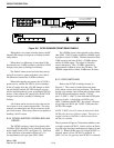
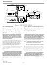
The OCXO drawer contains several alarms. For
all alarms, the following color scheme applies (see
Figure 6-6):
Flashing Red Failure
Yellow Standby
Green Active (OK)
If the main oscillator fails, its corresponding LED
turns from green (active) to flashing red (failure).
Consequently the LED for the remaining oscillator
changes from yellow (standby) to green (active).