


INSTALLATION
2-7
March 1999
Part No. 001-2009-600
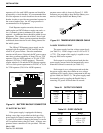
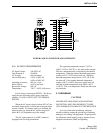
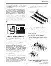
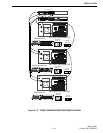
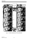
2.10 CONNECTING RECEIVE AND TRANSMIT
ANTENNAS
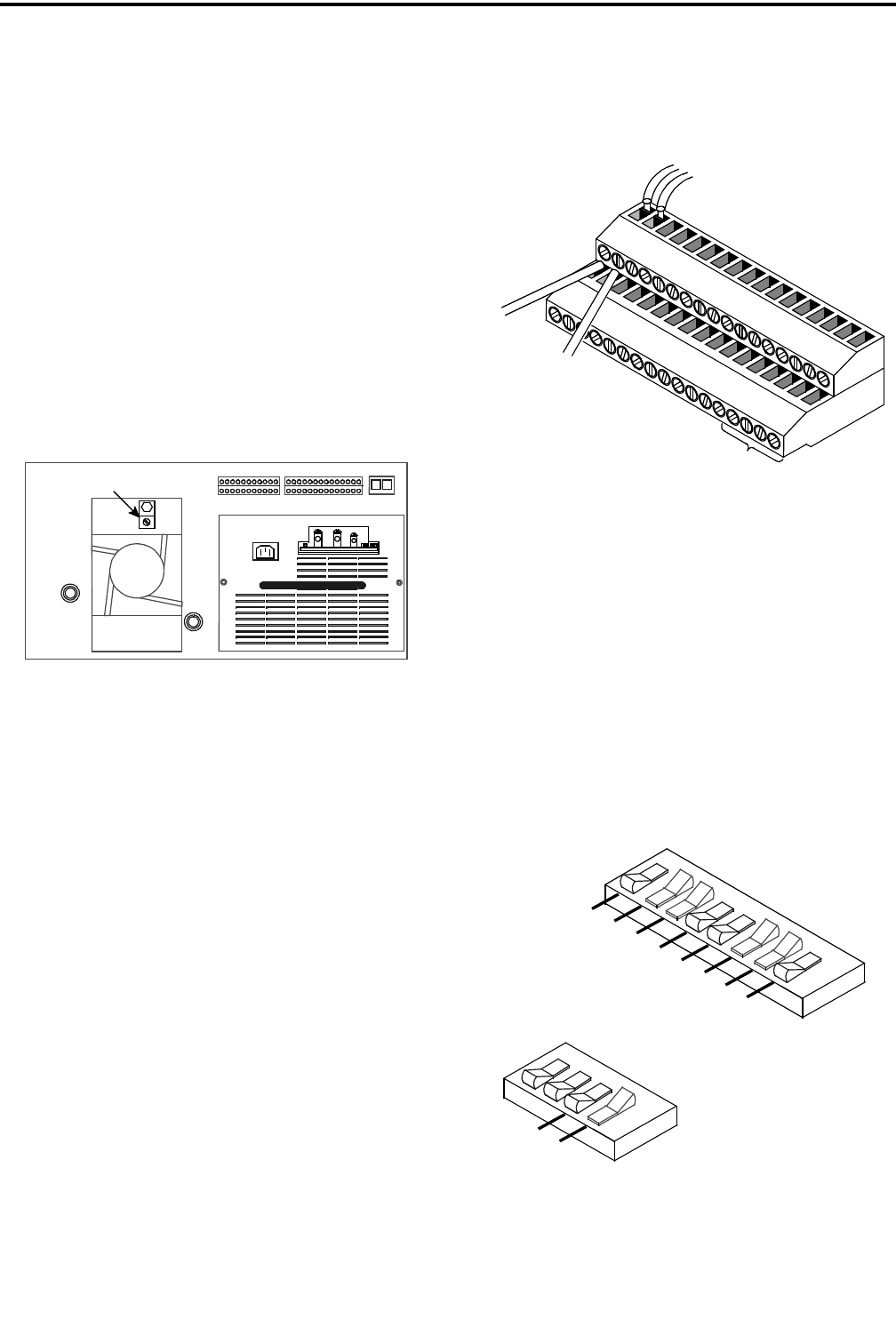
Receive and Transmit antenna connector loca-
tions are shown in Figure 2-7. Although each trans-
mitter and receiver could be connected to a separate
antenna, this is usually not done because of the large
number of antennas required by a multiple repeater
installation. Therefore, an antenna combining system
is usually used. An example of a combining system
for a five-channel system is shown in Figure 2-4. The
amount of power loss introduced by a combiner
depends on the type of combiner used. If it has a loss
of 3 dB, power output to the antenna is reduced by
half.
Figure 2-7 ANTENNA CONNECTIONS
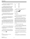
2.11 CONNECTING AUDIO/DATA LINK TO
SWITCH
A communication link of some type is required
between the Switch and each repeater. This link
allows the Switch to control the repeater and also
routes audio between the Switch and repeater. Various
types of links can be used, such as phone line, RF
transceiver, microwave, or fiber optic Refer to Section
1.14.3 for more information. The repeater connection
point is terminal block J2 on the back panel (see Fig-
ures 2-8, 2-12 and 2-13). The information which fol-
lows describes the installation of these links.
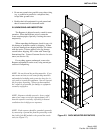
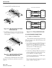
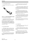
2.11.1 VOICE LINK
The voice link is always connected and it should
be a standard 4-wire, 600 ohm balanced voice- grade
link. It can be non-metallic, i.e. DC continuity is not
required. If the repeaters and Switch are located at the
same site, direct connection can be used as long as the
line is less than approximately 300 feet.
TX
RX
GROUND
Connect the voice link to terminals 1-2 and 3-4
(see Figure 2-8 and 2-12).
Figure 2-8 TERMINAL BLOCK J2
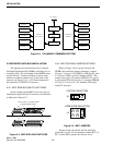
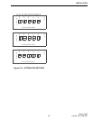
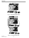
2.11.2 DATA LINK
One of these three methods can be used for
installing the data link.
NOTE: See Section 7 for Link Alignment.
1. Separate 4-wire link can be used that is similar to
that used for voice. The data is then encoded by
FSK and sent as tones.
Figure 2-9 MAC DIP SWITCH SETTINGS FOR
4-WIRE LINK
VOICE LINK CONNECTIONS
33
34
ALARMS
1 I
N
+
2 I
N
+
1 OUT +
2
O
UT +
2
O
UT
-
1 OUT -
2 IN -
1 IN -
AC FAIL
G
R
O
U
N
D
V
D
A
T IN
VOT AU
D
EXT MOD
T
X
S+
TXS-
RXS-
RXS+
M
B
MA
EA
EB
RIN
G
1
TIP 1
TIP
TXA
+
RX
A
+
T
X
A-
RXA
-
RIN
G
1
2
J2
3
P1-31
P1-63
P1-32
P1-64
4
TO SWITCH
FSK BLANK/BURST
G
R
O
U
N
D
+
1
5V
AC
C
+15V ACC
R
S
SI
EXT REQ1
O
N
2
1
8
7
6
5
4
3
O
N
2
1
4
3
R
X
S
-
(
G
N
D
)
R
X
S
-
R
X
S
+
(
A
U
D
I
O
)
R
X
S
+
(
F
S
K
)
R
X
S
-
(
G
N
D
)
T
X
S
-
TX
S
+
(
A
U
D
I
O
)
TX
S
+
(
FS
K
)
S
1
0
0
S
1
0
1
FS
K
TX
S
+