


ALIGNMENT AND TEST PROCEDURES
7-4
March 1999
Part No. 001-2009-600
7.3.4 TCXO FREQUENCY ADJUST
1. Tune TCXO Y401 for 3.5V DC ±0.05V DC at
U402, pin 1 (response time is very slow).
7.3.5 VCO TEST
1. The Synthesizer is programmed for 199 channels
above the transmit frequency.
2. Use the "Turn on carrier" button to key the Exciter.
3. Measure the voltage on U403, pin 6 (TP1). Voltage
should be < 7V DC and the Power Output +17.5
dBm ±0.5 dB.
4. Use the "Turn on carrier" button to unkey the
Exciter.
5. The Synthesizer is programmed for 199 channels
below the transmit frequency.
6. Use the "Turn on carrier" button to key the Exciter.
7. Measure the voltage on U403, pin 6 (TP1). Voltage
should be > 2.5V DC and the Power Output +17.5
dBm ±0.5 dB.
8. Use the "Turn on carrier" button to unkey the
Exciter.
7.3.6 TRANSMIT MODULATION ADJUST
1. Connect a 10 dB pad and modulation analyzer to
J402.
2. Press the "FM" and "3 kHz LPF" switches of the
modulation analyzer.
3. Inject a 1 kHz sine wave with a level of 400 mV
RMS into P100, pin 32 on the MAC.
NOTE: This test changes the Audio Deviation Limit.
Perform test in Section 7.6.6 to correct.
4. Adjust U149 for 707 mV RMS on P100, pin 29.
This waveform should be a "clean" sine wave.
5. Use the "Turn on carrier" button to key the Exciter.
6. Set R446 for ±1.5 kHz deviation.
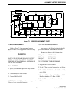
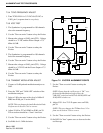
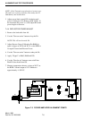
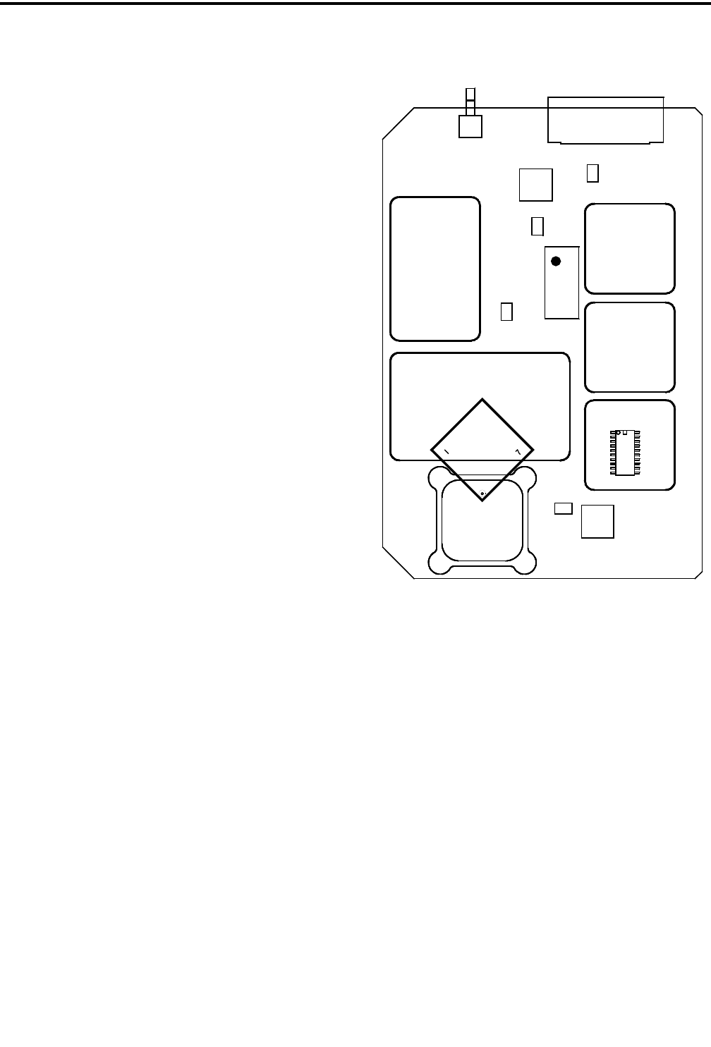
Figure 7-2 EXCITER ALIGNMENT POINTS
7. Use the "Turn on carrier" button to unkey the
Exciter.
NOTE: Ensure that the oscilloscope is "DC" cou-
pled and the Modulation Analyzer has the
3 kHz LPF switch set but NOT the 300 Hz HPF and
50 Hz HPF switches set.
8. Adjust U151 for a 2V P-P square wave on P100,
pin 29.
NOTE: This test changes the TX Data Level. Per-
form test in Section 7.6.6 to correct.
9. Use the "Turn on carrier" button to key the Exciter.
10.Set R425 for "best" square wave as observed on the
oscilloscope.
J402
U406
U402
Y401
R425
J401
U405
1
19
20
2
J403
U403
20
11
10
1
6
U404
R446
L404
A007