


CIRCUIT DESCRIPTION
6-17
March 1999
Part No. 001-2009-600
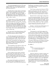
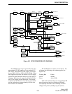
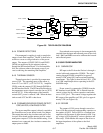
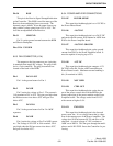
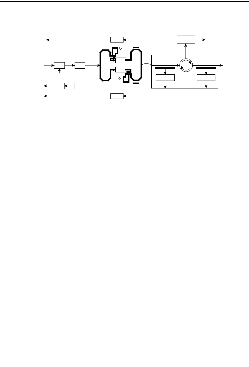
Figure 6-8 75W PA BLOCK DIAGRAM
RF IN
POWER CONTROL
DRIVER
THERMAL SENSOR
FINAL 2 POWER
FINAL 1 POWER
COMBINER
RF OUTPUT
LOW-PASS
FILTER
SENSE
POWER
PRE-DRIVER
AMP /
POWER
SENSE
U501 Q501
Q502
Q503
U502A U503
THERMAL
SENSORAMP
RF LOAD
U651A/B U652A/B
CIRCULATOR
2
2
SPLITTER
FORWARD
POWER
REVERSE
(REFLECTED)
POWER
FORWARD/REVERSE
POWER DETECTOR
CR502
CR503
6.4.4 POWER DETECTORS
Electromagnetic coupling is used to sample the
output of each final amplifier. The RF is then fed to a
rectifier to create a voltage indicative of the power
output. The outputs of CR502 (W510) and CR503
(W508) are monitored by the repeater software
through the RF Interface Board. If a final amplifier
fails, the software reduces the output power to pre-
vent overdriving the remaining final amplifier.
6.4.5 THERMAL SENSOR
Thermal protection is provided by temperature
sensor U503. The operating range of the sensor is
from -0° C to +100° C (+32° F to 212° F). Amplifier
U502A sends the output of U503 through WO509 to
the RF Interface Board. The RF Interface Board uses
the temperature sensor signal to turn the fan on (50°C)
and off (45°C). If the temperature of the heatsink
exceeds 90°C power is reduced 3 dB. When the heat-
sink exceeds 95°C the RF is shut down.
6.4.6 FORWARD/REVERSE POWER DETECT,
CIRCULATOR, LOW-PASS FILTER
The power amplifier output is directly coupled to
the forward/reverse power detect board via a jumper.
The output then enters the circulator and exits to the
low-pass filter board and the antenna jack for a mini-
mum power output of 75W at the default setting. If an
antenna is not connected, the circulator connects the
output power to R685.
Forward and reverse power is electromagnetically
coupled from the input and reflected ports of the circu-
lator. R663 and R680 are used to calibrate the forward
and reflected power.
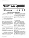
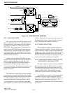
6.5 160W POWER AMPLIFIER
6.5.1 GAIN BLOCK
RF input to the PA from the Exciter is through a
coaxial cable and connected to WO509. The signal
coming through WO509 is amplified to approxi-
mately 0.25W using Q501 and associated matching
components. This signal is then fed into U501. U501
is an 18W amplifier/pre-driver operating in the 935-
940 MHz range.
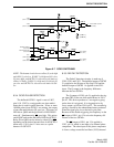
Power control is connected to WO505 from the
RF Interface board (RFIB). RF is filtered from the
control voltage line by various capacitors and induc-
tors to U501, pin 2. This control voltage regulates the
RF output of the amplifier on U501, pin 5 to approxi-
mately 15W (see Figure 6-9).
6.5.2 DRIVER
The output of U501 passes through several sec-
tions of 50 ohm microstrip and matching capacitors to
the emitter of Q502. Driver Q502 is a common base
amplifier with an output of approximately 60W. Sup-
ply voltage is RF bypassed by various capacitors and
microstrip. C568 matches the output of the driver to
the input impedance of the splitter to the final
amplifiers.