


CIRCUIT DESCRIPTION
6-6
March 1999
Part No. 001-2009-600
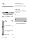
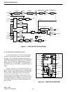
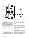
6.1.15 SYNTHESIZER
The synthesizer inputs/outputs are shown in Fig-
ures 6-1 and 6-3. The synthesizer output signal is the
receiver first injection frequency. This signal is pro-
duced by a VCO (voltage-controller oscillator). The
frequency of this oscillator is controlled by a DC volt-
age. This DC voltage is generated by integrating the
pulses from the phase detector in synthesizer chip
U209. This integration is performed by the synthe-
sizer loop filter which is made up of C805, C806 and
R804 in the VCO circuitry.
Frequencies are selected by programming
counters in U209 to divide by a certain number. This
programming is provided through J201, pins 12, 18
and 20. The frequency stability of the synthesizer is
established by the ±0.1 PPM stability of the high sta-
bility synthesizer loop consisting of OCXO, Synthe-
sizer U205, Y201 and Q206/Q207. The output from
the high stability loop is stable from -40°C to +70°C
(-40°F to +158°F).
The VCO frequency of A006 is controlled by a
DC voltage produced by integrating the phase detector
output pulses of U209. The phase detector senses the
phase and frequency of two input signals (fR and fV)
and causes the VCO control voltage to increase or
decrease if they are not the same. When the frequen-
cies are the same the VCO is "locked" on frequency.
One input signal to the phase detector in U209 is
the reference frequency (fR). This is the 17.5 MHz
TCXO frequency divided by the R (reference) counter
to the channel spacing or 12.5 kHz.
The other input signal to the phase detector in
U209 is from the VCO frequency divided down by the
"N" counter and prescaler in synthesizer U209 to
12.5 kHz. The "N" counter is programmed through
the synthesizer data line on J201, pin 20. U209 is pro-
grammed so that the phase detector input (fV) is iden-
tical to the reference frequency (fR) (12.5 kHz) when
the VCO is locked on the correct frequency.
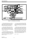
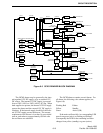
The synthesizer contains the R (reference), N,
and A counters, phase and lock detectors and counter
programming circuitry. Frequencies are selected by
programming the three counters in U209 to divide by
assigned numbers. The programming of these
counters is performed by circuitry in the Main Proces-
sor Card (MPC), which is buffered and latched
through the Interface Alarm Card (IAC) and fed into
the synthesizer on J201, pin 20 to Data input port
U209, pin 19.
Data is loaded into U209 serially on the Data
input port U209, pin 19. Data is clocked into the shift
registers a bit at a time by a low to high transition on
the Clock input port U209, pin 18. The Clock pulses
come from the MPC via the IAC to J201, pin 18.
As previously stated, the counter divide numbers
are chosen so that when the VCO is operating on the
correct frequency, the VCO-derived input to the phase
detector (fV) is the same frequency as the TCXO-
derived input (fR) which is 12.5 kHz.
The fR input is produced by dividing the 17.5
MHz TCXO frequency by 1400. This division is done
by the "R" counter in U209. The counter always
divides by 1400 regardless of the channel number.
This produces a reference frequency (fR) of 12.5 kHz.
Since the VCO is on frequency (receive frequency
minus 52.95 MHz) and no multiplication is used, the
channel frequencies change in 12.5 kHz steps and the
reference frequency (fR) is 12.5 kHz for all channels
selected by this receiver.
The fV input is produced by dividing the VCO
frequency using the prescaler and N counter in U209.
The prescaler divides by 64 or 65. The divide number
of the prescaler is controlled by the N and A counters
in U209.
The N and A counters function as follows: both
the N and A counters begin counting down from their
programmed number. When the A counter reaches
zero, it halts until the N counter reaches zero. Both
counters then reset and the cycle repeats. The A
counter is always programmed with a smaller number
than the N counter. While the A counter is counting
down, the prescaler divides by 65. Then when the A
counter is halted, the prescaler divides by 64.
Example: Assume a receive frequency of
898.5000 MHz (channel 200). Since the VCO is
52.95 MHz below the receive frequency it must be
845.5500 MHz for channel 200. To produce this fre-
quency, the N and A counters are programmed as fol-
lows:
N = 1056 A = 60