


CIRCUIT DESCRIPTION
6-31
March 1999
Part No. 001-2009-600
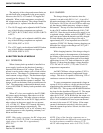
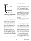
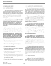
Figure 6-12 NO LOAD CHARGE VOLTAGE vs.
TEMPERATURE
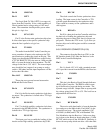
6.8.3 REVERSE BATTERY PROTECTION
To obtain reverse battery protection a number of
techniques were implemented. Q108/Q110 are
arranged in a Darlington configuration to isolate the
output capacitors C109-C111 from conducting in the
event the batteries are connected backwards. This cir-
cuit also provides a means to turn the battery charger
off in case the user wants to run the repeater off of
another DC source. S101 opens the base of Q105
which turns off Q104. CR111 is a green light emitting
diode (LED) located on the right hand side of the bat-
tery back-up module when looking at the front of the
power supply that tells the user the charger is in
charge mode and is marked "On".
To notify the user that the batteries are connected
improperly R101/CR101 are connected in series
across the batteries. CR101 is a red LED that lights
when the batteries are connected backwards and is
located on the left hand side of the battery back-up
module when looking at the front of the power supply.
This LED is marked "Reverse Bat.". CR113 elimi-
nates a path for the reverse battery current through the
relay and over/under voltage protection circuitry.
NOTE: Exceeding -30V across the battery back-up ter-
minals with the power supply on will destroy Q105.
30V
27.3V
25.2V
24V
-30° 0° +30° +60°
Temp (°C)
Charger Voltage
-55mV/°C
+22°
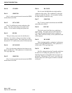
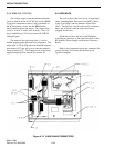
6.8.4 ENGAGING THE RELAY
The main purpose of the Battery Back-Up Mod-
ule (BBM) is that when the power supply loses AC
line voltage, a pair of series connected 12V lead acid
batteries (approximately 26.4V) or other 23-28.5V DC
source will engage to the supply allowing the repeater
to operate. To perform this function a voltage com-
parator (U101) is used to monitor the charge tap com-
ing from the power supply.
A 2.5V reference voltage is supplied to the com-
parator from U102. The transformer tap voltage is
smoothed and divided by CR114, C118, R116, R121
and R122. The values for these components were cal-
culated so that when the AC line voltage is dropped to
70V AC, the output of the comparator turns Q103/
Q102 on which in turn engages the relay K101. The
relay is capable of 30A which delivers the battery
energy to the power supply via W102 with the return
line being W103.
NOTE: When AC is restored, the relay disengages and
the charger automatically begins to charge the
batteries.
6.8.5 OVER/UNDERVOLTAGE SHUTDOWN
U101 is a quad comparator IC used to create the
overvoltage and undervoltage shutdown circuitry. If
the batteries are drained sufficiently enough such that
the voltage of the batteries drops below 20.3V DC the
output of the comparator goes low and turns Q102 off.
By turning Q102 off the batteries are switched out of
the circuit. The batteries cannot be switched back into
the repeater until the voltage rises to 22.6V DC. This
operation is in place to protect the repeater and the
batteries. In the event the batteries are over charged,
or the repeater is driven by the generator that has the
voltage set too high, the relay will disengage above
30.5V DC. In order to switch the batteries back to the
repeater, the voltage must drop below 29V DC.
In an overvoltage or undervoltage situation,
whether AC is present or not, the red LED (CR105)
lights until the problem is rectified. This light is
located on the right-hand side of the battery back-up
module when looking at the front of the power supply
and is marked BAT-BAD.