


INTRODUCTION AND OPERATION
1-7
March 1999
Part No. 001-2009-600
1.13.3 MAIN AUDIO CARD (MAC)
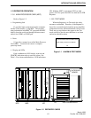
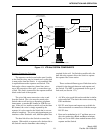
Refer to Figure 1-2.
• External Speaker Jack
J104 provides repeater audio output to an external
speaker. The local volume control adjusts the volume
level of this speaker.
• Speaker/Microphone Jacks
J102 provides audio input from a microphone.
J101 provides the receive audio to the microphone.
• Local On/Off/Volume Control
R236 provides control of the receive audio output
to J101 and J104. Turning this control clockwise past
the detente applies voltage to the local audio amplifier.
• A D Level Test Point
J100 provides audio/data level output for test
level checks.
• Ground
J103 is connected to ground for test equipment
when monitoring test point J100.
1.13.4 INTERFACE ALARM CARD (IAC)
Refer to Figure 1-2.
• Voltage Test Output
J502 provides a +15V test point on the IAC.
• Ground
J501 is connected to ground for test equipment
when monitoring voltage test point J502.
• A D Level Test Point
J500 provides a test point to monitor audio and
data levels, AC fail and thermal sensor.
• Power Supply On/Off Switch
S508 turns the power supply DC voltages on and
off from the IAC in the front of the repeater.
• Power Indicator
CR501 indicates the +5V supply is at normal
level and applied to the IAC. CR524 indicates -5V
supply is at normal level and applied to the IAC.
CR523 indicates the +15V accessory supply is at nor-
mal level. CR525 indicates that the +15V supply is at
normal level and applied to the IAC.
• CWID Indicator
This indicates that the CW Identification is being
transmitted on the lowest-frequency repeater. The
CWID is a continuous-wave (CW) transmission of the
station call letters in Morse Code to satisfy the station
identification requirement. The CWID is programmed
into the repeater memory. This indicator also is used
when an alarm is transmitted with Morse code.
• Hang Indicator
This indicates that the hang word is being trans-
mitted by the repeater. This word is transmitted on
calls in which the channel is held for the duration of
the call and not just for the duration of the transmis-
sion. The hang word tells the mobiles to stay on the
same channel and not re-access the system when
responding to a call.
• Switch Call Indicator
The Switch Call Indicator on the IAC shows that
a Switch-To-Mobile transmission is in progress (see
Figure 7-30.)
• Mobile Call Indicator
Mobile-to-repeater transmission in progress is
indicated by the Mobile Call Indicator.
• Xmit Indicator
This indicates that the repeater transmitter is
keyed by the logic.