


INTRODUCTION AND OPERATION
1-5
March 1999
Part No. 001-2009-600
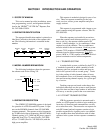
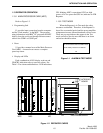
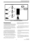
1.13 REPEATER OPERATION
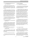
1.13.1 MAIN PROCESSOR CARD (MPC)
Refer to Figure 1-2.
• Programming Jack
J1 provides input connection from the computer
and the "flash memory" in the MPC. The program-
ming information in an IBM
PC programs the MPC
directly from the serial card through an interconnect
cable to the COM1 or COM2 port.
• Reset
S1 provides a manual reset of the Main Processor
Card (MPC). A manual reset causes a complete
power-up restart.
• Display and LEDs
Each combination of DS1 display read-out and
CR4/CR3 indication refers to an active alarm. See
Table 1-2 for alarms and definitions. LED indications:
CR1 blinking; MPC is operational, CR2 on; high
power, off is low power and CR5 on; indicates an LTR
Repeater.
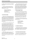
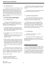
1.13.2 TEST MODE
When the Repeater is in Test mode the safety
measures are disabled. Therefore, if the Repeater is
keyed for an extended period and the power amplifier
temperature increase, thermal shutdown will not occur.
There are pop-up windows that appear in the Test
mode screens to alert the user that there is an alarm
and action should be taken.
Figure 1-1 ALARM IN TEST MODE
NOTE: Safety measures are disabled
RF Thermal Sense Alarm Condition Exists
Ok
Figure 1-2 REPEATER CARDS
IACMACMPC
J502
J501
J500
GRN
YEL
YEL
RED
RED
PROG
JACK
RESET
ON/OFF/VOL
LOCAL
MIC
SPKR
EXT SPKR
XMIT
MOBILE
SWITCH
HANG
CWID
+15V
GND
TP
J103
J100
GND
A D
LEVEL
R236
J102
J101
J104
J1
S1
CR1
CR2
CR4
DS1
S508
RF INTERFACE
BOARD
EXCITER/RECEIVER
PA
CR3
CR5
+5V
-5V
+15V
+15V ACC