


CIRCUIT DESCRIPTION
6-42
March 1999
Part No. 001-2009-600
stable DC bias voltage for U126C/D is required
because these stages are DC coupled to the transmit
TCXO (see Section 6.2.2) and changes in bias voltage
can cause fluctuations in the transmit frequency.
U126C/D form a low-pass filter that attenuates
square-wave harmonics in the data signal above 150
Hz to prevent interference with the audio band. From
this filter the signal is fed to summing amplifier
U129B and combined with the transmit audio signal.
The output of U129B is fed to Transmit Modulation
Mute Gate U118D. This gate is controlled by A/D
processor U111/latch U106. When enabled, transmit
audio and data are passed to the Exciter modulation
input and the transmit TCXO.
When needed, the External Modulation input on
P100, pin 11 is fed to External Modulation Mute Gate
U118C. Gate U118C is controlled by A/D processor
U111/latch U106. When enabled, this gate passes the
modulation on pin 11 to summing amplifier U129B
and gate U118D to the modulation input of Exciter.
The repeater on the lowest frequency channel in
each system must periodically transmit the station call
letters as a continuous-wave identification encoded by
Morse Code. This identification is programmed with
the Edit Parameters software.
The CWID output is controlled by A/D processor
U111/latch U107. This output is fed to CWID tone
generator U100B/A and turns the tone generator on
and off to create the Morse Code. From the tone gen-
erator the signal is fed to bandpass filter U129A. This
filter passes the 800 Hz fundamental present in the
signal. The output of the filter is jumpered by P106
on J106, pins 2/3 and P107 on J106, pins 4/5 to the
summing amplifier and applied to gate U118D, and to
the modulation input of the Exciter.
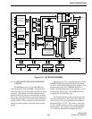
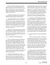
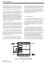
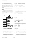
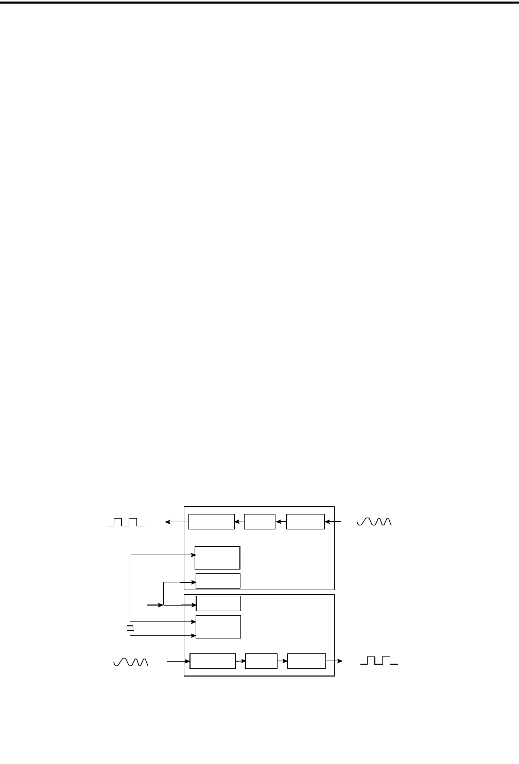
6.12.12 FSK MODEM
The function of the FSK Modem U109 is to con-
vert digital data into tones that can be sent on a phone
line or some other type of audio link. Modem U110
receives tones from the audio link and converts them
back to digital data (see Figure 6-16). The FSK
Modem is only used when connecting the repeater to
an Switch.
This modem is programmed to operate in the
Bell 202 Main Loopback mode by the M0-M1 pins.
In this mode, a space (logic 0) is represented by a
2200 Hz tone, and a mark (logic 1) is represented by a
1200 Hz tone. The same tones are used for transmit
and receive. Therefore, the transmit and receive filters
in the modem are set for the same frequency. This
form of frequency modulation in which data is
encoded by shifting the frequency of tones is called
Frequency Shift Keying (FSK). The modulation is
phase-continuous which means that no interruption of
the waveform occurs when the frequency changes.
Figure 6-16 MODEM BLOCK DIAGRAM
CLOCK DIVIDERS
XTAL OSCXTAL/CLK
TRANSMIT FILTER
OUTPUT BUFFER
FSK MOD
RX/TX DATA
RE-TIMING
MOD CONTROLM1
CLOCK DIVIDERS
XTAL OSC
XTAL/CLK
RECEIVE FILTER
EQUALIZER
FSK
RX/TX DATA
RE-TIMING
MOD CONTROLM0
XTAL
RX IN
RXD
TX OUT
TXD
DEMOD
U110
U109