


SERVICING
8-6
March 1999
Part No. 001-2009-600
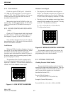
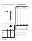
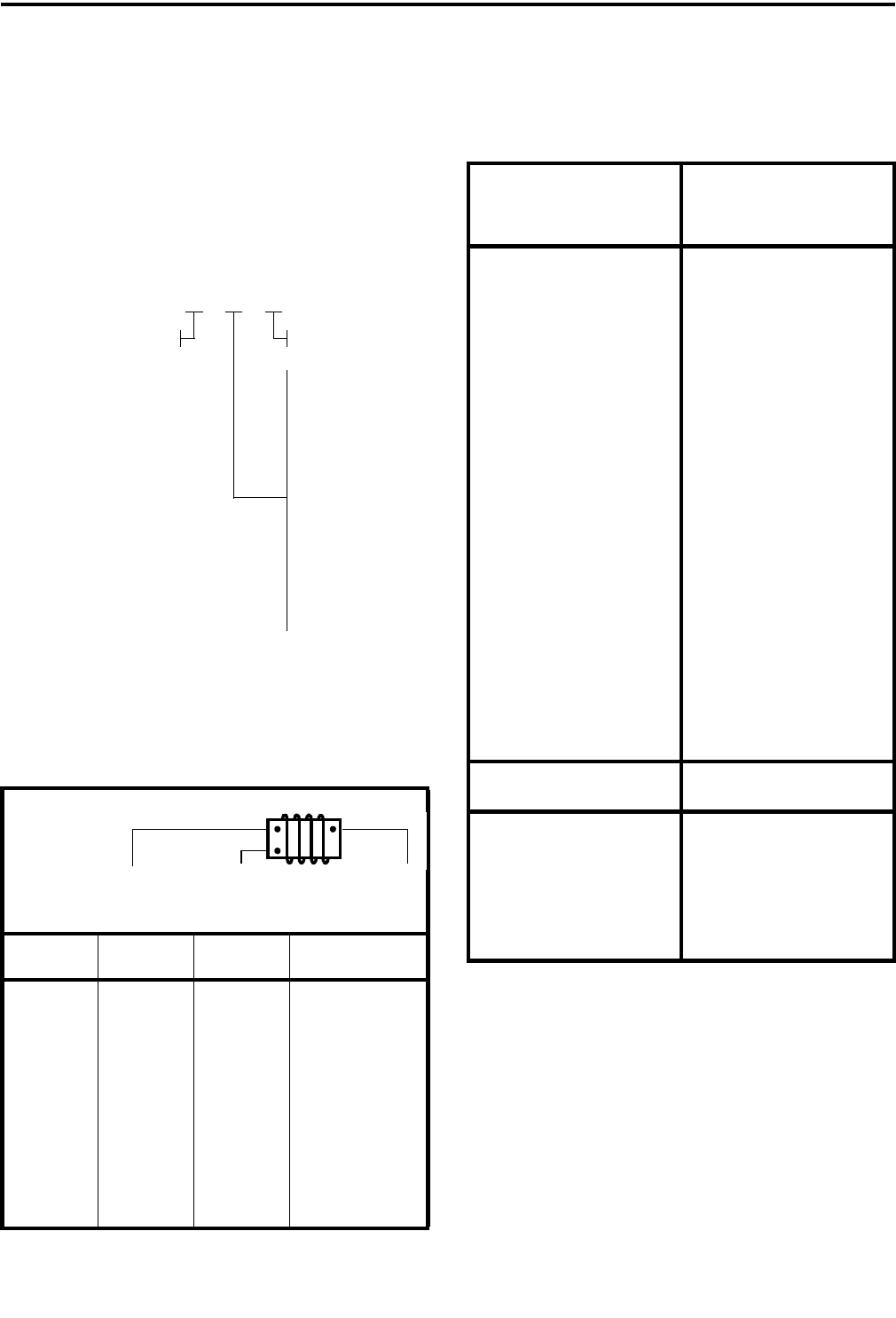
Some resistors with a ±1% tolerance are identi-
fied by a 4-digit number and others may not have a
marking. When identified with a 4-digit number, the
first three digits are the value and the fourth is the mul-
tiplier.
Example: 5761 5.76k ohm
Figure 8-5 3-DIGIT RESISTOR
8.6.5 CHIP TRANSISTORS AND DIODES
Surface mounted transistors and diodes are identi-
fied by a special number that is shown in a table on
Page 10-1.
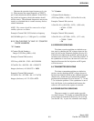
Table 8-1 CHIP INDUCTOR IDENTIFICATION
Color 1st Digit 2nd Digit Multiplier
(Last PN Digit)
Black 0 0 1 (7)
Brown 1 1 10 (8)
Red 2 2 100 (9)
Orange 3 3 1000 (0)
Yellow 4 4 10,000 (1)
Green 5 5 100,000 (2)
Blue 6 6 ---
Violet 7 7 ---
Gray 8 8 ---
White 9 9 0.1 (6)
9 = 0.1
8 = 0.01
3 = 1k
4 = 10k
5 = 100k
6 = 1M
7 = 10M
2 = 100
1 = 10
0 = 0
MultiplierValue in ohms
XXX
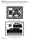
Table 8-2 CERAMIC CHIP CAP
IDENTIFICATION
American EIA Standard Japanese EIA Standard
First Letter/
Number
Value (pF)
First Letter/
Number
Value (pF)
A
B
C
D
E
H
I
J
K
L
N
O
R
S
T
V
W
X
Y
Z
3
4
7
9
10
11
12
13
15
16
18
20
22
24
27
30
33
36
39
43
47
51
56
62
68
75
82
91
A
B
C
D
E
F
G
H
J
K
L
M
N
P
Q
R
S
T
U
V
W
X
Y
Z
1.0
1.1
1.2
1.3
1.5
1.6
1.8
2.0
2.2
2.4
2.7
3.0
3.3
3.6
3.9
4.3
4.7
5.1
5.6
6.2
6.8
7.5
8.2
9.1
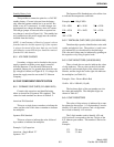
Color Multiplier
Second
Number
Multiplier
Orange 0.1 0 1
Black 1 1 10
Green 10 2 100
Blue 100 3 1000
Violet 1000 4 10,000
Red 10,000 5 100,000