


CIRCUIT DESCRIPTION
6-3
March 1999
Part No. 001-2009-600
The 450 kHz second IF is then fed to ceramic fil-
ter Z205, then to the IF amplifier. The center fre-
quency of Z205 is 450 kHz with a -6 dB bandwidth of
9 kHz used to attenuate wideband noise. The limiter
amplifies the 450 kHz signal 92 dB which removes
any amplitude fluctuations.
From the limiter, the signal is fed to the quadra-
ture detector. An external phase-shift network con-
nected to U202, pin 8, shifts the phase of one of the
detector inputs 90° at 450 kHz (the other inputs are
unshifted). When modulation occurs, the frequency of
the IF signal changes at an audio rate as does the phase
of the shifted signal. The detector, which has no out-
put with a 90° phase shift, converts the phase shift into
an audio signal. Z213 is adjusted to provide maximum
undistorted output from the detector. The audio signal
is then fed out on U202, pin 9.
6.1.7 WIDEBAND AUDIO AMPLIFIER
U203B amplifies the detected audio and data sig-
nal. R280/R263 set the gain of the amplifier and
R256/R262/R284 provide a DC reference level. C220
bypasses the 450 kHz IF signal and C240 bypasses
other frequencies. The output signal is adjusted by
R264 and fed to J201, pin 9.
6.1.8 RSSI AMPLIFIER
U202, pin 13 is an output from an internal RSSI
(receive signal strength indicator) circuit that provides
a current proportional to the strength of the 450 kHz IF
signal. The RSSI output is buffered through U203A
and the level is adjusted by R261. The DC output
signal is then fed to J201, pin 7.
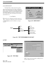
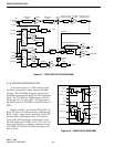
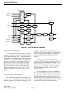
6.1.9 HIGH STABILITY SYNTHESIZER
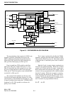
The high stability synthesizer inputs/outputs are
shown in Figures 6-1 and 6-3. The synthesizer con-
tains the R (reference), N, and A counters, phase and
lock detectors and counter programming circuitry.
The phase detector output of Synthesizer U205, pin 6
is a 10 kHz pulse waveform from 0 to 5V. This signal
is integrated to provide a DC tuning voltage for the
TCXO. The DC tuning voltage provides the TCXO
with the ±0.1 PPM stability of the OCXO (Oven Con-
trolled Crystal Oscillator) see Section 6.3.
The phase detector input signals are generated by
counters in U205 that are programmed to divide by a
certain number. This programming is provided
through J201, pins 18, 19 and 20. The frequency sta-
bility of the High Stability synthesizer (TCXO output)
is established by the ±0.1 PPM stability of the OCXO
drawer. The output from the high stability loop is
stable from -40°C to +70°C (-40°F to +158°F).
The phase detector in U205 compares the phase and
frequency of two input signals; fR and fV. The phase
detector generates a 0 to 5V signal. The pulse width
of this signal varies depending on the phase difference
between fR and fV. This signal is filtered (integrated)
by C245/C246/C247/R245/R246 to provide a DC tun-
ing voltage for the TCXO. The voltage at Y201, pin 2
is set for 3.5V when the high stability loop is locked.
This is done by adjusting the tuning screw in TCXO
Y201.
One input signal to the phase detector in U205 is
the reference frequency (fR). This frequency is
1.25 MHz divided by the R (reference) counter to
10 kHz. The 1.25 MHz signal comes from the OCXO
drawer to J202. The signal is then fed to two buffer/
amplifiers. Q203 provides the OCXO signal to the
Receiver and Q204 provides the OCXO signal to the
Exciter. The inputs to Q203/Q204 are matched to
50 ohms by R239/R321. DC blocking to Q203 is pro-
vided by C224. Bias for Q203 is provided by R219,
R217, R218, R220 and R221. C313, C225 and C226
provide RF bypass. The output of Q203 is coupled to
U205, pin 20 by C305.
DC blocking to Q204 is provided by C227. Bias
for Q204 is provided by R224/R222/R223/R225/
R226. C314, C228 and C229 provide RF bypass. The
output of Q204 is coupled to the Exciter high stability
synthesizer U401 by C230 (see Section 6.2.5).
The other input signal to the phase detector in
U205 is from the TCXO frequency divided by the "N"
counter and prescaler in U205. The "N" counter is pro-
grammed through the synthesizer data line on J201,
pin 20. U205 is programmed so that the phase detec-
tor input (fV) is identical to the reference frequency
(fR). The programming for the High Stability synthe-
sizer does not change with channel selection.