


2-1
March 1999
Part No. 001-2009-600
SECTION 2 INSTALLATION
2.1 INTRODUCTION
Information in this section tells how to set up the
repeater for operation in an LTR-Net system. It is
assumed that the repeater has been previously aligned
at the factory or as described in the alignment proce-
dure in Section 7.
Even though each repeater is thoroughly aligned
and tested at the factory, it is good practice to check
performance before it is placed in service. This
ensures that no damage occurred during shipment and
that the repeater is otherwise operating properly. Per-
formance testing is described in Sections 7.2, 7.3, 7.4
and 7.5.
2.1.1 SITE PREPARATION AND ANTENNA IN-
STALLATION
Site preparation and antenna installation are not
within the scope of this manual. Basic installation
requirements are discussed in the "Dealer Guide To
Site Preparation", Part No. 004-8000-100. Factory
installation is also available. Contact your Johnson
representative for more information.
2.2 ENVIRONMENT
The following conditions should be considered
when selecting a site for the Repeater.
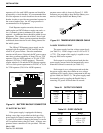
Operating Temperature
-30°C to +60°C (-22°F to +140°F).
Humidity
Less than 95% relative humidity at 50°C.
Air Quality
For equipment operating in a controlled environ-
ment with the Repeaters rack mounted, the airborne
particles must not exceed 30 µg/m
3
.
For equipment operating in an uncontrolled envi-
ronment with the Repeaters rack mounted, the air-
borne particles must not exceed 100 µg/m
3
.
NOTE: If the Repeater is installed in an area that
exceeds these environmental conditions, the site
should be equipped with air filters to remove dust and
dirt that could cause the equipment to overheat.
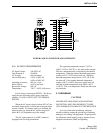
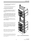
2.3 VENTILATION
The RF modules and the power supply are
equipped with fans, controlled by thermostats, that
force air through the equipment for cooling. The air
flow is from the front to the back of the equipment.
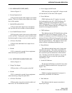
This permits the Repeaters to be stacked or rack
mounted (see Figure 2-3). There are a few consider-
ations when installing Repeaters to provide adequate
air circulation.
• The Repeaters should be mounted with a minimum
of 6 inches clearance between the front or back of
the cabinet for air flow. The power supply requires
a minimum of 18 inches at the back of the Repeater
for removal.
NOTE: Repeaters should not touch. Leave a mini-
mum of one empty screw hole (approximately 1/2")
between repeaters vertically, especially for bottom
ventilation slots in high power repeaters.
• Cabinet enclosures must provide air vents for ade-
quate air circulation.
• Temperature and humidity must be considered
when several Repeaters are installed at a site. This
might require air conditioning the site.
2.4 AC POWER
The AC power source to the Viking VX Repeater
can be 120V AC or 240V AC. Nothing need be done
to the power supply for 240V AC operation. How-
ever, a 240V AC outlet requires that the 120V AC
power plug be replaced. A locking AC power cord is
provided for the supply.
The 120V AC cord is a standard 3-wire grounded
cord used with a standard AC wall outlet. The outlet
must be capable of supplying a maximum of 328W (-
632) or 680W (-634). With the nominal 120V AC
input, the source must supply 3A for each 75W