


CIRCUIT DESCRIPTION
6-47
March 1999
Part No. 001-2009-600
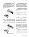
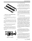
Figure 6-20 4 I/O J2 ALARM OUTPUTS
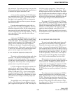
6.13.3 ISOLATED INPUTS
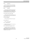
The isolated alarm inputs are provided via a ter-
minal block on the back of the repeater (see Figures 6-
19 and 6-20).
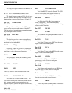
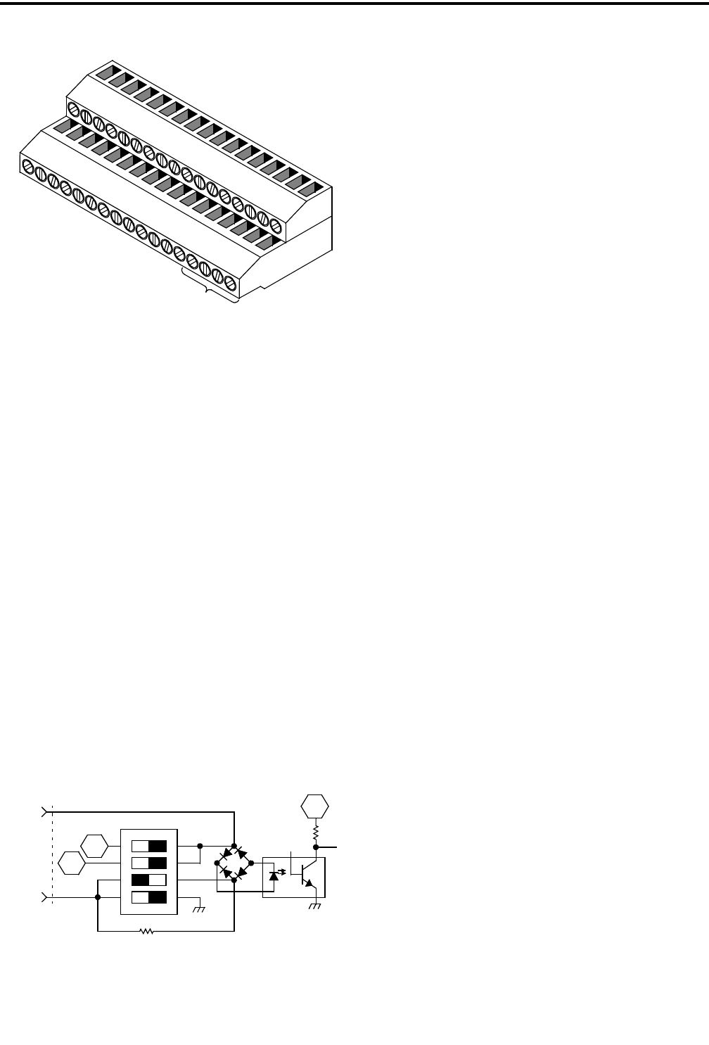
The isolated inputs are driven by either AC or DC
signals. The active high inputs can be set by switches
to be polarity sensitive, non-polarity sensitive or add a
resistance in series to dissipate unused power (see Fig-
ure 6-21).
The active low inputs can also be set for either
+5V or +15V operation when a ground closure is
required to provide an active alarm.
Standard 12V/24V AC control transformer out-
puts can be accepted as well as DC voltages. This
input voltage range is 5-24V RMS. External resistors
connected in series may be used to extend the input
voltage range.
Figure 6-21 S500-S503
6.13.4 ALARM INDICATORS
There are three forms of alarm indicators from
the repeater. One form is the two red LEDs and dis-
play combination on the MPC. Refer to Table 1-2 for
the combinations and definitions of the active alarms.
Another form is the output relay to the terminal
blocks at the rear of the repeater where outputs can be
wired to external devices or to alarm inputs.
The third form is the output relay and to transmit
a 15-character description of the alarm over-the-air to
a remote location. The description is sent in Morse
code with a transmit ID assigned during programming.
A transceiver programmed with this ID can monitor
the repeater and alert the system owner when an alarm
occurs.
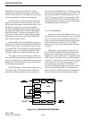
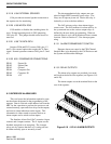
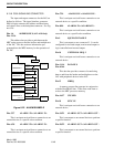
6.13.5 ALARM FUNCTIONS
The alarms can be configured in various modes to
alert the system owner to conditions and hazards with
the equipment and the repeater site facility. A few of
the possibilities are shown in Figure 6-22. In this
example the input alarm 2 of Repeater 1 is connected
to the door of the building, input alarm 3 of Repeater 5
is connected to the fire alarm system, the AC fail
alarm (#16 see Table 1-2) is mapped to alarm 2 output
so it can be transmitted (see Figure 4-13) and the out-
put alarm 1 of Repeater 1 is connected to the input
alarm 1 of Repeater 2 and so on until the output alarm
1 is fed back to the input alarm 1 of Repeater 1. Then
the RF Shutdown alarm (#32) is mapped for alarm 1 in
each repeater. This configuration allows Repeater 2 to
give an alarm when Repeater 1 has an RF Shutdown
alarm output, etc.
The input alarms are given a 15-character
description during programming and a Transmit ID.
These are used when an input alarm is activated to
send a Morse code message consisting of the descrip-
tion over the air to a monitoring transceiver pro-
grammed with this ID.
There are 40 internal alarms that can be included
in the output alarm configuration (see Table 1-2).
These alarms can also be programmed to send an out-
put as shown in the cross reference screen of the alarm
configuration menu (see Figure 4-13). Among these
alarms are the thermal sense from the PA and the AC
fail alarm output on the terminal block at the rear of
the repeater to activate the battery backup.
33
34
A
L
A
R
M
S
1 IN +
2
I
N
+
1 O
U
T +
2
OU
T
+
2 OU
T
-
1 O
UT
-
2 IN
-
1 IN
-
AC
FAIL
1
2
J2
1
2
3
45
6
7
8+5V
+15V
P500
ALARM +
ALARM -
ON
+5V