


INSTALLATION
2-8
March 1999
Part No. 001-2009-600
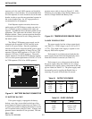
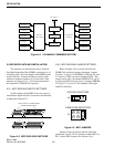
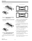
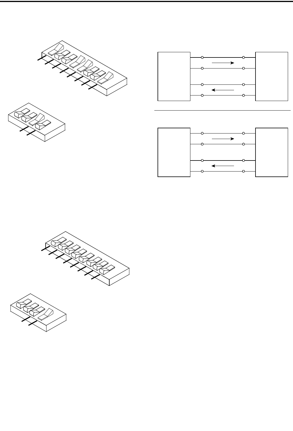
2. A separate RS-232 serial link can be used.
Figure 2-10 MAC DIP SWITCH SETTINGS
FOR RS-232 LINK
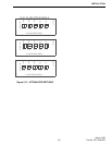
3. The FSK data can be sent over the voice link using
a Blank and Burst technique. No separate data link
is then required.
Figure 2-11 MAC DIP SWITCH SETTINGS
FOR BLANK AND BURST LINK
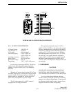
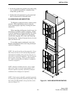
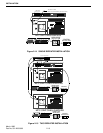
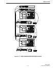
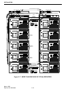
Select the type of link being used, refer to Figure
2-8 and 2-12 and make the connections to terminals 1-
2 and 3-4.
Figure 2-12 LTR-Net VOICE/DATA LINK
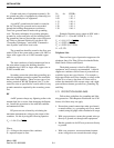
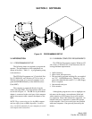
2.12 OCXO DRAWER CONNECTIONS
2.12.1 VIKING VX CONNECTION
These guidelines should be followed when using
2009 series repeaters with a 2000 OCXO drawer, Part
No. 023-2000-925.
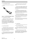
• One 1.25 MHz output on the 2000 OCXO drawer is
connected to the 1.25 MHz Input on each 2009
Repeater. Up to eight 2009 series repeaters can be
connected to the 1.25 MHz Output ports.
This level is approximately 0 dBm.
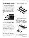
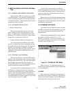
• If connection to additional 2009 series repeaters is
necessary, additional 8-Way Splitter Shelves, Part
No. 023-2000-924, are added as required.
All shelves are connected to the 1.25 MHz output
ports of the 2000 OCXO drawer.
The level at the splitter shelf output ports is approx-
imately -10 dBm. See Figure 2-13.
O
N
2
1
8
7
6
5
4
3
O
N
2
1
4
3
R
X
S
-
(
G
N
D
)
R
X
S
-
R
X
S
+
(
A
U
D
I
O
)
R
X
S
+
(
FS
K
)
R
X
S
-
(
G
N
D
)
TX
S
-
TX
S
+
(
A
U
D
I
O
)
TX
S
+
(
FS
K
)
S
1
0
0
S
1
0
1
F
S
K
T
X
S
+
O
N
2
1
8
7
6
5
4
3
O
N
2
1
4
3
R
X
S
-
(
G
N
D
)
R
X
S
-
R
X
S
+
(
A
U
D
I
O
)
R
X
S
+
(
F
S
K
)
R
X
S
-
(
G
N
D
)
TX
S
-
T
X
S
+
(
A
U
D
I
O
)
TX
S
+
(
F
S
K
)
S
10
0
S
10
1
F
S
K
TX
S
+
P1-64
P1-63
J2-4
J2-3
P1-32
P1-31
J2-2
J2-1
TxA+
TxA-
RxA-
RxA+
RxA+
RxA-
TxA-
TxA+
PRIMARY
RxA
PRIMARY
TxA
VOICE LINK CONNECTIONS
DATA LINK CONNECTIONS
RxA
TxA
RxS+
RxS-
TxS+
TxS-
RxS+
RxS-
TxS+
TxS-
SECONDARY
SECONDARY
J2-13
J2-14
J2-15
J2-16
P1-27
P1-28
P1-59
P1-60
SWITCH
LTR- Ne t
REPEATER
SWITCH
LTR- Ne t
REPEATER