


CIRCUIT DESCRIPTION
6-36
March 1999
Part No. 001-2009-600
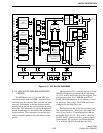
The operating speed of the microprocessor is set
by an 11.059 MHz clock generated by Y2. This clock
frequency is divided down by an internal divider to
provide a machine cycle time of 1.08 µs. Most pro-
gram instructions are executed in one machine cycle
and none require more than four machine cycles.
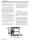
The microprocessor U13 communicates with the
main processor (U27) through U9 and U10. U9 is a
Transmit FIFO (First In First Out) and U10 is a
Receive FIFO. This combination makes up an asyn-
chronous parallel-to-parallel interface to the Main
Processor.
Microprocessor U13 also calculates the current
system priority for the channel. This priority is from
the programming software responses and the current
priority is sent to the main processor. U13 also reads
repeater number and channel number information in
memory. U13 also determines the current free
repeater and includes that information in the data sent
to the main processor.
6.11.4 CHIP SELECT DECODERS
These select the peripheral chip to read from or
write to.
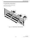
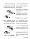
6.11.5 P1 SIGNAL CONNECTOR
This is the signal interface connector P1 (64 pin)
that connects the Address and Data buses and control
lines to the backplane connector.
Pins 1-10 Address Bus
Pins 33-42
This provides a path between the MPC main pro-
cessor and the external memory on the MPC and the
other cards in the Controller. This bus retrieves infor-
mation programmed into memory for the operation of
the repeater.
Pins 11-14 Data Bus
Pins 43-46
This provides a means of transferring data to and
from the CPU on the MPC, memory storage on each
card and peripheral devices in and out of the MAC and
IAC.
Pin 15 MREQ
A memory request line operates in conjunction
with the Read/Write lines. These provide the ability to
read from or write to the main processor memory on
the MPC.
Pin 16 MSTB
A memory strobe line is used during MPC main
processor Read/Write operations to external memory
on the MPC and other cards plugged into the
backplane.
Pins 17-20 UNUSED
Pin 21 LPTT
The Logic Push-To-Talk is an open collector from the
Controller. It has a sink capability of 20 mA and a max-
imum voltage rating of 18V. The transmitter should
produce power when this pin is a logic low. Transmit
indicator is on the IAC and is controlled independently
of the LPTT.
Pin 22 SWITCH TX DATA
This is the RS-232 data to the Switch. The CIM
receives confirmation of all requests made to the
repeater and sends information the repeater receives.
The data rate is 1200 baud.
Pin 23 SWITCH RX DATA
This is the RS-232 data from the Switch. The
CIM controls the repeater with restart, enable and dis-
able, executes requests to read and write to the
repeater’s memory and tells the repeater transmit code,
hang or send turn-off. The data rate is 1200 baud.
Pins 24/56 HSDB+/HSDB-
This interconnects all repeaters to provide an
exchange of information. This control technique is
called distributive processing and eliminates a separate
system controller at each site. Information on this bus
indicates which repeaters are in use and also which
mobiles are using the system. This information is used
by the repeater to encode data messages to mobiles
that are monitoring that channel. These messages also
include information on which repeater is free and cur-
rent system priority.