


7-1
March 1999
Part No. 001-2009-600
SECTION 7 ALIGNMENT AND TEST PROCEDURES
7.1 OCXO AND TEST EQUIPMENT FREQUEN-
CY STABILITY
The receiver and transmitter frequencies are
locked to the 1.250000 MHz reference frequency from
the local oscillator drawer. This frequency is stable to
within ±0.1 PPM from -30°C to +60°C as required by
the FCC. To properly align the IF sections of the
receiver, the signal generator must have similar stabil-
ity. Since most test equipment is not this stable, a sep-
arate reference oscillator that is stable to ±0.05 or
±0.01 PPM may be needed to clock the signal genera-
tor and frequency counter.
Adjustment of the 1.250000 MHz reference fre-
quency probably should not be attempted for the same
reason. Unless the communications monitor has a sta-
bility of ±0.01 PPM or better, the repeater frequency
may be more correct than that of the monitor. If it is
certain that one or both oscillators in the local oscilla-
tor drawer are off frequency, there is an adjusting
screw on the oscillators that is used to change the fre-
quency slightly. Adjustment should only be per-
formed when the ambient temperature is near the cali-
bration reference of 25°C (77°F).
If power is removed from the local oscillator
drawer, the oscillators require a minimum restabiliza-
tion period of 30 minutes. No frequency-critical
adjustments should be attempted until the oscillator
frequency has stabilized.
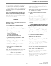
7.2 RECEIVER ALIGNMENT
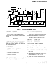
Refer to Figure 7-1 for component locations.
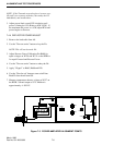
Refer to Figure 7-9 for equipment needed and setup
diagram.
7.2.1 PRE-TEST
1. Preset L201, L202, L203, L204, L206, L223 and
L224 tuning screws about 1/4 inch above the top of
the casting.
2. Preset L202 and L205 tuning screws so they are just
barely above their tightening lock nuts.
7.2.2 VOLTAGE MEASUREMENTS
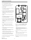
Apply power to the Receiver by plugging the 20-
pin cable from the RF Interface Board into J201 (see
Figure 7-1).
Measure the voltages at the following pins.
U206, pin 1 +12V DC ±0.4V
U207, pin 1 +12V DC ±0.4V
U208, pin 1 +6V DC ±0.2V
U210, pin 1 +12V DC ±0.4V
7.2.3 PROGRAM TUNE-UP CHANNEL
1. Using the PC and software, program the Synthesizer
for the Receive channel number.
2. Tune the VCO helical L220 for +4.5V DC ±0.05V
on U209, pin 6 or TP2.
3. Alternately tune L223 and L224 in 1/2-turn to 1-turn
increments until a voltage is measured on J201, pin
13 or TP5. At that time, tune L223 for a peak, then
L224 for a peak.
4. Retune L223 and L224 for a peak at J201,
pin 13.
NOTE: The Channel Number, Channel Frequency and
Synthesizer Frequency appear at the bottom of the
screen.
7.2.4 TCXO FREQUENCY ADJUST
1. Set Y201 (TCXO) for 3.5V DC ±0.05V DC at TP1
(response time is very slow).
7.2.5 VCO TEST
2. The Synthesizer is programmed for 199 channels
above the Receive Channel.
3. The voltage on U209, pin 6 (TP2) should be
< 7.5V DC.
4. Record the voltage on J201, pin 13 (TP5) ____.