CIRCUIT DESCRIPTION
6-40
March 1999
Part No. 001-2009-600
6.12.6 RECEIVE AUDIO PROCESSING
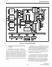
The receive audio signal from the receiver is fed
into the MAC on P100, pin 27. When it is a call that
does not need to be routed to the Switch (i.e. most
mobile-to-mobile calls utilizing only that repeater),
Repeat Gate U153C is enabled and the receive audio
signal is routed through Transmit Option Gate U158C
to the input of the transmit audio buffer U164B to be
retransmitted. Repeat Gate U153C is controlled by
processor U111 through latch U107. A logic 1 on the
control input causes the signal to be passed, and a
logic 0 causes the signal to be blocked.
Amplifier U166A provides amplification of the
receive audio signal fed to the Switch. The gain of
U166A is set so that if an RF signal is received that
has a reference deviation level, the Switch receives a
specified level also. No limiting occurs.
When the audio received from the mobile must
be routed to the Switch (i.e. calls to a dispatcher or
another system), receive audio gate U116B is enabled
and passes the signal.
When the received audio must be routed to the
backplane (i.e. for other cards), Receive Voice Gate
U115B is enabled by processor U111/latch U108 and
passes the audio signal to amplifier U120B. Receive
To Backplane (RX TO BP) U115C is enabled and
passes the amplified audio to the backplane.
When the audio received must be routed to the
external speaker or speaker/microphone, Local Audio
Mute Gate U114D is enabled by U111/latch U108.
The audio is passed to local audio output amplifier
U132. The gain of U132 is adjusted by the local audio
volume control and the on/off switch.
6.12.7 VOTER AUDIO
This is not a Simulcast operation, however, when
used the Receive audio from the voter receiver comes
into the MAC on P100, pin 25. Amplifier U120A sets
the gain of the signal and the output is routed to Voter
Audio Mute Gate U115A. The gate is controlled by
A/D processor U111/latch U108. If the gate is
enabled, the audio goes to the Receive Mute Gate
U113C and passes throughout the MAC Card.
6.12.8 COMPANDOR OPTION
The compandor option enhances the receive and
transmit audio when used in conjunction with the
Telephone Interface Card (TIC) in LTR-Net systems.
The filtered Receive Audio passes through the
Receive Mute Gate U113C to the expander input on
A301, pin 1. The expand output of A301, pin 2 is
coupled to the audio outputs by U114C.
The transmit comes from TX-VOICE P100, pin
32, passes through the TX Voice Gate U158A to the
expander input on A301, pin 5. The compressed out-
put of A301, pin 4 is passed to the Transmit Audio
Buffer.
6.12.9 TRANSMIT AUDIO
PTT switch (Q101/Q102) provides local micro-
phone Push-To-Talk (PTT) indication to U105. U105
then tells U111 via the data bus that the local micro-
phone PTT has been activated.
U164A amplifies the microphone audio signal to
provide the correct input level to U164B. Local
Microphone Mute Gate U117C is controlled by A/D
processor U111/latch 106. The function of U117C is
to mute the local microphone audio when the local
microphone PTT switch is pressed. This prevents
interference if the microphone remains live when the
PTT switch is pressed.
Transmit Intercom Gate U117A is controlled by
A/D processor U111/latch U157. When enabled, this
gate passes local microphone audio to Main Audio
Amplifier U166A and to the Main Audio To Switch
output. This provides an intercom between the
repeater site and Switch console operator.
Buffer U164B combines the microphone audio
signal from U164A with the audio signal from the
Repeat Gate U153C.
U127B/C form a high-pass filter that attenuates
frequencies below 300 Hz to prevent interference with
the Multi-Net data applied at U129B. 6 dB per octave
pre-emphasis is provided by an RC combination
before the signal is fed to U127D.


