


1-1
March 1999
Part No. 001-2009-600
SECTION 1 INTRODUCTION AND OPERATION
1.1 SCOPE OF MANUAL
This service manual provides installation, opera-
tion, programming, service, and alignment informa-
tion for the VIKING
VX LTR-Net
®
Repeater, Part
No. 242-2009-632/634.
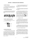
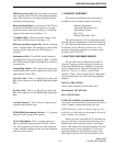
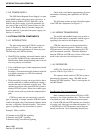
1.2 REPEATER IDENTIFICATION
The repeater identification number is printed on a
label that is affixed to the inside of the repeater cabi-
net. The following information is contained in that
number:
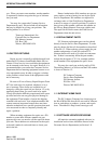
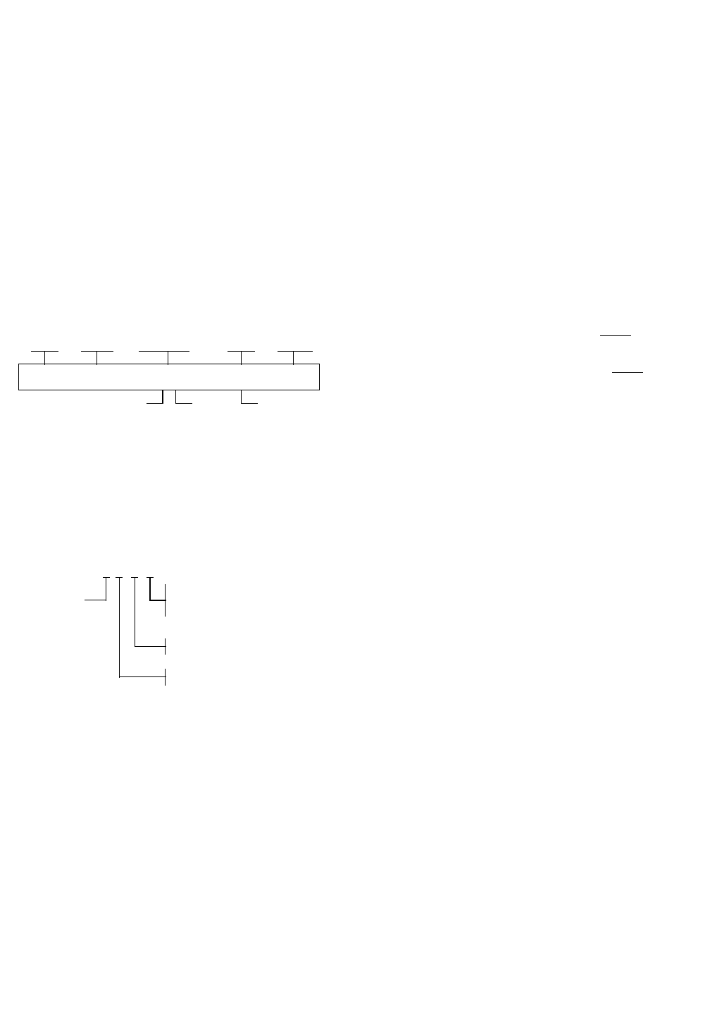
1.3 MODEL NUMBER BREAKDOWN
The following breakdown shows the part num-
ber scheme used for the Viking VX.
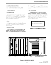
1.4 REPEATER DESCRIPTION
The VIKING VX 900 MHz repeater is designed
for operation in a LTR-Net and LTR system. It oper-
ates on the 900 MHz channels from 935-940 MHz
(repeater transmit). The repeater receive frequencies
are 39 MHz below these frequencies (896-901 MHz).
Channel spacing is 12.5 kHz and RF power output is
adjustable from 25 to 75 watts (Part No. 242-2009-
632) or 75-160W (Part No. 242-2009-634) with the
high power amplifier.
This repeater is modular in design for ease of ser-
vice. There are separate assemblies for the logic
cards, receiver
, exciter, power amplifier and power
supply sections.
This repeater is programmed with a laptop or per-
sonal computer using the repeater software, Part No.
023-9998-459.
When the repeaters are installed in an environ-
ment that contains small airborne particles, e.g. grain
dust or salt fog, the repeater cabinets need to be
sealed. A heat exchanger, i.e. air conditioner, is then
required to cool the cabinets. The air conditioners
must be suited for the environment. Each
low power
repeater (75W) requires >1200 BTU/hr dissipation to
maintain exterior cabinet temperature. Each
high
power (160W or 175W) requires >2100 BTU/hr dissi-
pation to maintain exterior cabinet temperature.
1.4.1 TRUNKED SYSTEM
A trunked radio system, as defined by the FCC, is
a "method of operation in which a number of radio
frequency pairs are assigned to radios and base sta-
tions in the system for use as a trunk group". Trunk-
ing is the pooling of radio channels where all users
have automatic access to all channels reducing waiting
time and increasing channel capacity for a given qual-
ity of service.
Trunking concepts are based on the theory that
individual subscribers use the system a small percent-
age of the time and that a large number of subscribers
will not try to use the system at the exact same time.
1.4.2 LTR-NET TRUNKED SYSTEM
LTR-Net repeater operation is automatic and is
similar to a LTR repeater in which a logic module per-
forms the call functions and communicates over-the-
air to subscriber units. There must be one repeater for
each RF channel and each repeater contains a logic
module responsible for signaling on its own channel.
Logic modules then share information with all other
repeaters in the system via inter-repeater communica-
tion.
20XXX
Week Year A= Waseca
Number
WarrantyPlant
Date
Manufacture
Letter
Revision
12345A324A
Repeater
ID
X242-2009-
2 = 25 - 75W
3
3 = 12.5 kHz
6
6 = LTR-Net
4 = 75 - 160W
9 = 900 MHz