


LTR-Net PROGRAMMER
4-11
March 1999
Part No. 001-2009-600
4.6.1 EXCITER
This menu selection walks through the Exciter
alignment windows. Refer to Section 7.3 for the
Exciter alignment and Figure 7-2 for an alignment
points diagram and Figure 7-10 for a test setup of the
Exciter.
4.6.2 POWER AMPLIFIER
This menu selection walks through the Power
Amplifier and RF Interface Board alignment windows.
Refer to Sections 7.4 and 7.5 for the PA and RFIB
alignment in this manual and Figures 7-3, 7-4, and 7-5
for alignment points diagrams and Figures 7-11 and 7-
8 of the Power Amplifier.
4.6.3 RECEIVER
This menu selection walks through the Receiver
alignment windows. Refer to Section 7.2 for the
Receiver alignment in this manual and Figure 7-1 for
an alignment points diagram and Figure 7-9 of the
Receiver.
4.6.4 FULL REPEATER
This menu selection walks through the full
repeater alignment windows. The Receiver and
Exciter portions are performance tests and adjust-
ments. The Audio and Data portions are level adjust-
ments for the Main Audio Card (MAC). Refer to Fig-
ure 7-28 for an alignment points diagram for the
MAC.
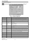
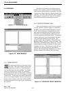
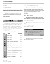
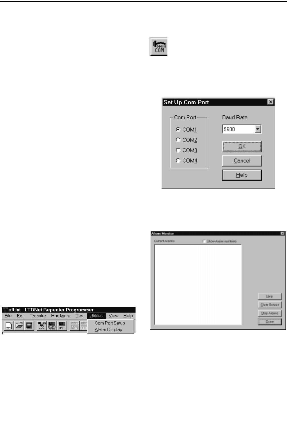
4.7 UTILITIES
Figure 4-26 UTILITIES MENU
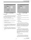
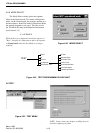
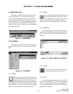
4.7.1 COM PORT SETUP
This menu selection has an equivalent icon in
the toolbar. This menu selection or icon allows
changes to the COM port or baud rate used to
send and receive data from the attached Repeater MPC.
An interface cable connects the Repeater to the comput-
er (see Figure 4-27).
Figure 4-27 SETUP COM PORT
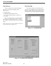
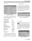
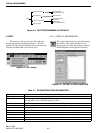
4.7.2 ALARM DISPLAY
Figure 4-28 ALARM MONITOR