INTRODUCTION AND OPERATION
1-2
March 1999
Part No. 001-2009-600
System control is accomplished by the exchange
of data messages between radio and repeater. The
LTR-Net system trunks up to 20 channels by utilizing
continuous subaudible digital data applied to the RF
carrier simultaneously with voice modulation. There-
fore, no dedicated control channel is required and all
channels are used for voice communications for maxi-
mum system efficiency. Each radio is assigned a
Home Channel which sends system commands to
specified radios. There are normal words and special
function words. The special function words are used
to initiate special calls; Telephone, Unique ID, and
Data by Unique ID. The special function words are
also used for command calls: Interrogate, Kill, Reas-
sign, Electronic Serial number Authentication, Regis-
tration, De-Registration, etc.
Since each repeater is responsible for signaling
on its own channel, this approach lends itself well to a
distributed processing logic controlled approach
requiring only a small logic unit within each repeater.
These processors share information over a communi-
cation path. This architecture permits each repeater to
be autonomous. A failure in one repeater leaves the
remainder of the system intact and operational.
The repeaters may be connected to a larger sys-
tem. This allows the system to perform some of the
previously mentioned calls. The Switch may commu-
nicate from one LTR-Net Locality to another. The
system equipment may be centrally located or distrib-
uted at each Locality. A Locality is a set of repeaters
that are interconnected to pool the channels in a
trunked channel group.
1.5 LTR-Net SIGNALING
The repeater covered by this manual utilizes
LTR-Net signaling. This signaling provides advanced
features such as 65504 Unique ID codes, five levels of
access priority, home channel backup, and over-the-air
mobile reprogramming. LTR-Net signaling and
repeater control is provided by the Main Processor
Card. The repeater connects to the 3000 Series Switch
using a phone line or some other type of link. The
Switch provides overall system control (see Sections
1.14 and 5 for more information on LTR-Net equip-
ment and features).
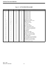
1.6 ACCESSORIES
The accessories available for the Viking VX LTR
repeater are listed in Table 1-1. A brief description of
some of these accessories follows.
Table 1-1 VIKING VX REPEATER
ACCESSORIES
Accessory Part No.
2000 Series Service Kit
1
250-2000-230
Battery Back-Up Option
2
023-2000-835
Reference Oscillator Splitter Shelf
3
023-2000-924
Reference Oscillator Adapter Kit
4
023-2000-923
Redundant OCXO 561-0006-012
Companding Module 023-2000-940
2’ RG-58 BNC M-M HSDB cable 023-4406-505
6’ RG-58 BNC M-M HSDB cable 597-3001-214
Custom Frequency Programming & Setup 023-2000-100
PC Programmer PGMR Software 023-9998-459
Service Microphone 589-0015-011
50 ohm Termination HSDB 023-4406-504
Telewave Combining Systems
5-channel 115V AC
6
585-1163-115
5-channel 230V AC
6
585-1163-125
10-channel 115V AC
7
585-1163-110
10-channel 230V AC
7
585-1163-120
Duplexer (High Power Only) 585-1157-101
RF Lightning Protector
Type-N Lightning Arrestor 585-0898-001
Polyphaser™ 585-0898-005
Floor Mount 19” Open Rack***
7’ with accessories
5
, setup and test 023-2000-216
7’ 6” with accessories
5
, setup and test 023-2000-217
8’ with accessories
5
, setup and test 023-2000-218
AC Power Distribution
AC Power Strip 115V AC (1 per 2 rptrs) 597-1004-010
AC Power Stirp 230V AC (1 per 2 rptrs) 023-2000-212
1
Includes: extender card, extender cables, TIC bias cable
and programming cable.
2
+26V DC input with cable.
3
Required for more than eight channels.
4
Interface to existing systems.
5
Accessories include all mounting hardware, rack ground
bar and wire to repeaters.
6
These systems use two antennas and one additional rack
(combining rack is included).
7
These systems use three antennas and two additional racks
(combining rack is included).


