LTR-Net PROGRAMMER
4-5
March 1999
Part No. 001-2009-600
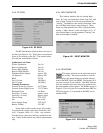
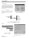
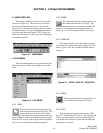
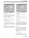
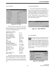
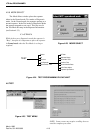
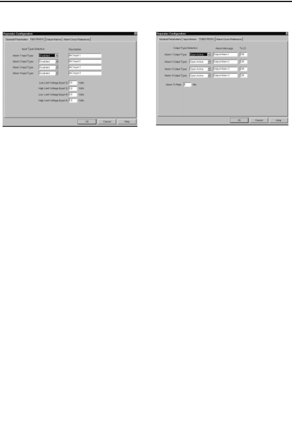
Figure 4-10 INPUT ALARMS
Input Alarms
There are four Input Alarms that can be activated
by external devices (see Section 6.13). These inputs
can be Disabled, Energized or De-Energized. Alarms
3 and 4 can also be Analog Inputs.
• Disabled - The input alarm line is inactive.
• Energized - An open circuit external to the repeater
activates the alarm.
• De-energized - A closed circuit external to the
repeater activates the alarm.
• Analog - Select the Low and High Limit pairs to trip
an Analog Input Alarm. The High Limit must be
greater in value than the Low Limit (0.0V-5.0V in
0.1V steps).
• Alarm Description - This is a text string (up to 15
characters) to describe the alarm. The description is
automatically changed on the Cross Reference Win-
dow.
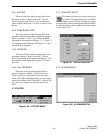
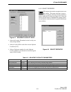
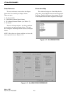
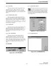
Figure 4-11 OUTPUT ALARMS
Output Alarms
Select the operation of the Output Alarm. The
available types are:
• Open Active - An active alarm opens (no contact)
the output lines.
• Closed Active - An active alarm closes (contact) the
output lines.
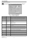
• Alarm Message
This is a text string (up to 15 characters) to
describe the alarm. This text string is sent via Morse
code if the alarm input is programmed with a Tx ID
and an output is selected in the Cross Reference menu
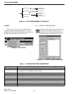
(see Figure 4-13). The Alarm Message is automati-
cally transferred to the Cross Reference window.
• Transmit ID
Each of the 4-alarm outputs can be assigned a
Group ID from 1-239. The default setting is 238,
0 (zero) for disabled. This Group ID and the Repeater
number identify an alarm that is active. This ID can
be programmed into a transceiver so that when the
alarm is active, the alarm description is received in
Morse code.
• Alarm Transmit Rate
This sets the time interval for transmitting the
alarm message in Morse code (0-30 min). If more
than one alarm is active, this is the inter-alarm time.


