


CIRCUIT DESCRIPTION
6-18
March 1999
Part No. 001-2009-600
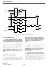
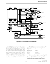
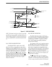
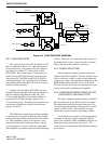
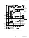
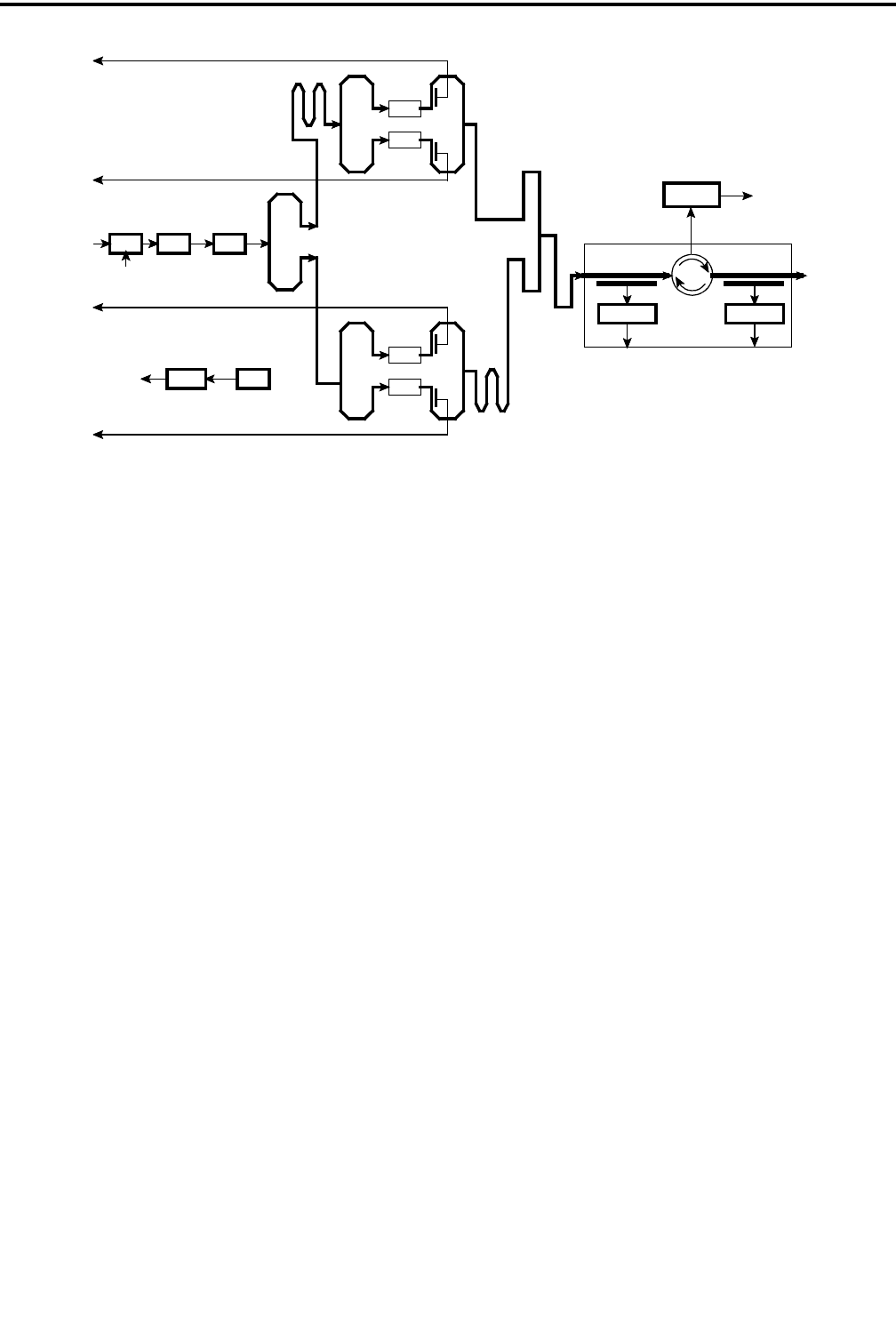
Figure 6-9 160W PA BLOCK DIAGRAM
RF IN
DRIVER
THERMAL SENSOR
COMBINER
RF OUTPUT
LOW-PASS
FILTER
VSWRFORWARD
U501
U502A U503
THERMAL
SENSORAMP
RF LOAD
U651A/B U652A/B
DIRECTIONAL COUPLER
CIRCULATOR
GAIN BLOCK
Q502
Q701
Q702
POWER SENSE
DELAY LINE
1/2 WAVE
POWER SENSE
POWER SENSE
POWER SENSE
RF 4
RF 3
RF 2
RF 1
SPLITTER
SPLITTER
SPLITTER
COMBINER
1/2 WAVE DELAY
1/4 WAVE TRANSFORMER
COMBINER
Q703
Q704
Q501
POWER
CONTROL
6.5.3 FINAL AMPLIFIERS
The output of the driver is DC blocked by C552
and is connected to the first 70.7 ohm splitter with a
50 ohm microstrip. One output of the first splitter is
sent directly to another 70.7 ohm splitter to feed
Q703/Q704. The second output is connected to the
splitter driving Q701/Q702 through a half-wave 50
ohm microstrip. The 60W output of Q701/Q702 is
combined through a 70.7 ohm quarter-wave Wilkin-
son combiner and fed through a 50 ohm microstrip to
the final 50 ohm combiner.
Outputs from amplifiers Q703/Q704 are fed to
the final combiner through 50 ohm microstrip that is a
half-wavelength longer than the other side. The
25 ohm output impedance of the final combiner is
transformed to 50 ohms through a quarter-wave,
35.35 ohm microstrip. The output of the quarter-wave
transformer is fed directly into the forward power
detector via W510.
The Wilkinson combiners provide the capability
to split the drive input and combine the final outputs
while maintaining isolation between the final amplifi-
ers. Each combiner consists of two quarter- wave
transmission lines and a balancing resistor. During
normal operation, a signal of relatively equal phase
and amplitude is present on both ends of the balancing
resistor. Therefore, no current flows and no power is
dissipated in the resistor. If one final fails, the other
final of the pair would continue to function.
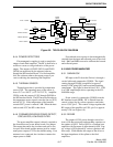
6.5.4 POWER DETECTORS
Electromagnetic coupling is used to detect the
output of each final amplifier. The detected RF is then
fed to a rectifier to create a voltage output indication
of the power output. The outputs are monitored by the
RFIB and the station software. If any of the finals
fails, the software will reduce the output power to pre-
vent overdriving the remaining final amplifier.
6.5.5 FORWARD/REVERSE POWER DETECT,
CIRCULATOR, LOW-PASS FILTER
The power amplifier output is directly coupled to
the forward/reverse power detect board via a jumper.
The output then enters the circulator and exits to the
low-pass filter board and the antenna jack for a power
output of 160W (±7W). If an antenna is not con-
nected, the circulator connects the output to R685.
Forward and reverse power is electromagnetically
coupled to the detectors on the input and reflected
ports of the circulator. R663 and R680 are used to cal-
ibrate the forward and reverse sense levels. The
sensed levels are connected to the RF Interface Board
and software.