


ALIGNMENT AND TEST PROCEDURES
7-3
March 1999
Part No. 001-2009-600
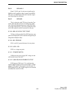
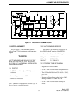
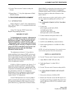
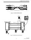
Figure 7-1 RECEIVER ALIGNMENT POINTS
L220
L201
L202
L203L204
L205
L206
L223
L224
TP5
L207
L229
L209
L211
L231
L225
Z213
R284
R261
R264
U206
TP3
TP4
J201
1
2
19
20
TP6
U207
Y201
TP1
U208
U210
U208
1
4
58
1
4
58
A006
TP2
7.3.2 VOLTAGE MEASUREMENTS
Apply power to the Exciter by plugging the 20-
pin cable from the RF Interface Board into J401.
Measure the voltages at the following pins.
U406, pin 1 +12V DC ±0.4V
U405, pin 1 +5V DC ±0.2V
U404, pin 7 +3.5V DC ±0.1V
7.3.3 PROGRAM TUNE-UP CHANNEL
1. Program the Transmit Channel.
2. Use the "Turn on carrier" button to key the Exciter.
3. Tune VCO helical L404 for 4.5V ±0.05V on U403,
pin 6 (TP1).
4. Measure the Power Output of the Exciter at J402.
Reading should be +17.5 dBm ±0.5 dB.
5. Use the "Turn on carrier" button to unkey the
Exciter.
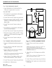
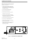
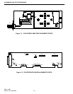
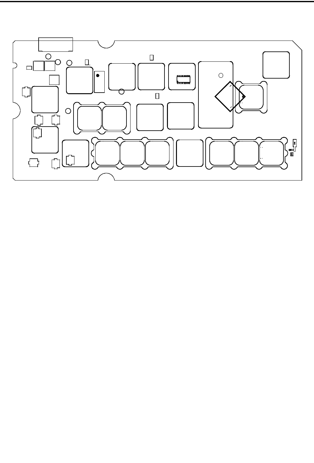
7.3 EXCITER ALIGNMENT
Refer to Figure 7-2 for component locations.
Refer to Figure 7-10 for equipment needed and setup
diagram.
WARNING
SAFETY MEASURES ARE DISABLED IN TEST
MODE. ALARMS ARE ACTIVE. HOWEVER,
FEATURES SUCH AS THERMAL SHUTDOWN IN
THE PA ARE DISABLED.
7.3.1 PRETEST
1. Set TCXO modulation adjust R425 fully counter-
clockwise.
2. Connect the power meter to J402.
3. Connect OCXO to J403.
NOTE: 2000 Series OCXO must be powered up for 1/
2 hour or longer to stabilize frequency.