


LTR-Net PROGRAMMER
4-4
March 1999
Part No. 001-2009-600
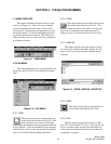
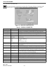
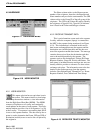
4.3.3 REPEATER INFORMATION
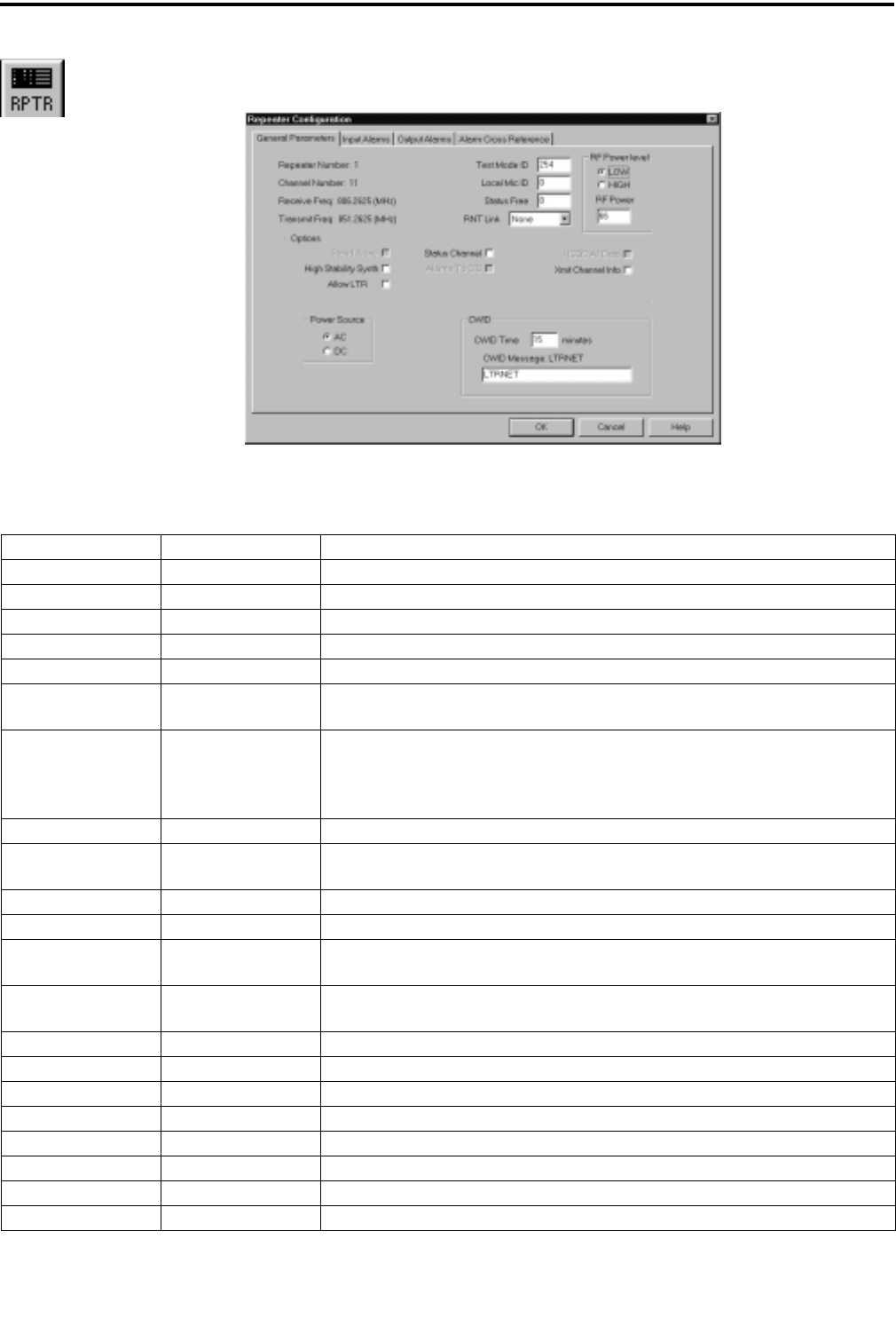
This menu selection has an equivalent icon in the toolbar. This menu selection or icon brings up the
parameter pages for the selected repeater. It allows entry of information specific to this repeater.
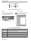
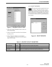
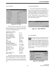
Figure 4-9 REPEATER CONFIGURATION
Table 4-3 GENERAL PARAMETERS
Repeater Number 1-20 Repeater number was established in Locality Configuration.
Channel Number 1-399 Channel number was established in Locality Configuration.
Receive Frequency Frequency was determined by channel number in Locality Configuration.
Transmit Frequency Frequency was determined by channel number in Locality Configuration.
Test Mode ID 1-239 Group ID transmitted when the Repeater is in the Test Mode.
Local Mic ID 1-239 Group ID transmitted when the local microphone PTT is active.
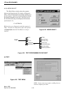
Status Free 0=never
20=always
When the number of free channels falls below this value, Status Channel can be
used for voice.
RNT Link None
FSK
Dig
BnB
Data Signaling type for 3000 Series Switch.
Frequency Shift Keying
RS-232
Blank and Burst (FSK)
RF Power Level Low, High Low=25-75, High=75-160. Power level in watts for transmit power output.
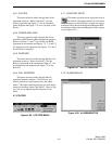
Options Stand Alone Selected if the repeater is permitted to operate without a connection to the 3000
Series Switch.
High Stability Synth Selected if the Receiver and Transmitter use the High Stability Synthesizer.
Allow LTR Selected if standard LTR protocol is allowed.
Status Channel One repeater at a Locality is designated to transmit update information for all
calls occurring at that Locality. Normally not assigned as a Home repeater.
Alarm to CIB Routes repeater alarms to the Channel Interface Bus to be detected by the Call
Processor and the System and Subscriber Manager.
HSDB All Data Repeater receives all the data on the High Speed Data Bus.
Xmit Channel Info Repeater sends updates on all repeaters installed in this Locality.
Power Source AC, DC The type of primary power source for the Repeater.
CWID Time 0=disabled, 1-30 min The time interval between CWID transmissions.
CWID Message Station call letters This is the FCC station call letters (15 characters/numbers).
OK Saves the current selections shown and closes the window.
Cancel Disregards all changes on any of these four screens and closes the window.
Help Displays the Help screen for the parameters in this window.