


INTRODUCTION AND OPERATION
1-8
March 1999
Part No. 001-2009-600
1.13.5 POWER SUPPLY
The 2000 Series Repeater Power Supply is a quad
output 800W supply with power factor correction. A
battery back-up module, PN 023-2000-830, can be
added to the power supply to provide automatic bat-
tery revert in the event of AC power failure (see Sec-
tion 1.4) The Battery Back-Up module charges the
batteries when AC is present at the power supply (see
Section 1.5 and 8.6).
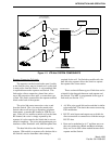
1.14 LTR-Net SYSTEM COMPONENTS
1.14.1 INTRODUCTION
The main components in a LTR-Net system are
shown in Figure 1-3. An LTR-Net system can be
designed to meet the requirements of almost any user.
The following are LTR-Net features.
• With LTR-Net signaling, advanced features such as
up to 65504 Unique ID codes, automatic mobile
identification, home channel backup, and five levels
of access priority are available.
• Users of different types of radio equipment can talk
to each other.
Example: a Conventional mobile channel could talk
to a mobile operating on a LTR-Net (trunked)
900 MHz channel.
• Wide area radio coverage can be provided so that a
mobile could talk to another mobile that is using a
repeater that may be hundreds of miles away. That
repeater may be part of the same LTR-Net system or
another LTR-Net system. Phone line or other types
of links can be used to provide the communication
path.
LTR-Net systems are not restricted to a specific
type of signaling. Example: an entire LTR-Net system
could be designed using Conventional channels which
use tone- or digitally-controlled squelch. The various
types of signaling can also be mixed in a system.
Example: There could be:
10-channels using LTR-Net signaling
5-channels using LTR
signaling
5-channels using Conventional signaling
Check with your Johnson representative for more
information concerning the capabilities of LTR-Net
systems.
The following sections provide a brief description
of the LTR-Net components see Figure 1-3.
1.14.2 MOBILE TRANSCEIVERS
The mobile and handheld transceivers used in a
LTR-Net system must be compatible with the type of
signaling in use and also the frequency range.
LTR-Net transceivers can be programmed for
LTR and Conventional operation. However, some
LTR transceivers can only be programmed for LTR
and Conventional operation. The main difference
between LTR-Net and LTR only versions of the same
model is the software in the microprocessor.
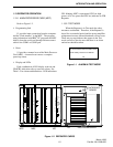
1.14.3 REPEATERS
NOTE: The Summit QX does not require a
separate LTR-Net logic drawer.
The repeater model used in a LTR-Net system is
determined by frequency range, 900 MHz use the
Summit QX 2009 repeaters. There is one repeater for
each RF channel.
Inter-Repeater Data Communication
Data communication between LTR-Net or LTR
repeaters is via a high-speed data bus. This bus cable
is installed in a daisy-chain manner between repeat-
ers. If both LTR-Net and LTR repeaters are located at
a Locality, only like types are connected together. Up
to 20 LTR-Net or 20 LTR repeaters can be intercon-
nected (see Section 1.9 for connecting the data bus).