


CIRCUIT DESCRIPTION
6-32
March 1999
Part No. 001-2009-600
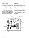
6.8.6 BBM FAN CONTROL
The voltage supply to the thermal measurement
circuit is taken from the 26.5V DC line into the BBM.
A precision temperature sensor U106 is mounted on
the PC board near a screw into the BBM bracket
which transfers heat to the sensor. The output of this
sensor is 10 mV/°C with a ±1% accuracy. This volt-
age is amplified by U105 with resistors R153/R154
setting the gain.
The output of this gain stage (pin 1) is fed to
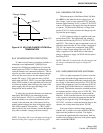
another gain stage that performs as a comparator. The
output (pin 7) will go high when the heatsink tempera-
ture reaches 45°C and will go low when the tempera-
ture goes below 35°C. This output is sent to the power
supply through Q106 to turn the fan on and off.
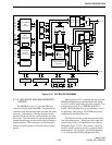
6.9 CARD RACK
The card rack provides slots for up to eight logic
cards; including Main Processor Card (MPC), Main
Audio Card (MAC) and the Interface Alarm Card
(IAC). The IAC has a notch in the card to accommo-
date a pin in Slot-8 so that no other card can be
plugged into this slot.
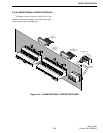
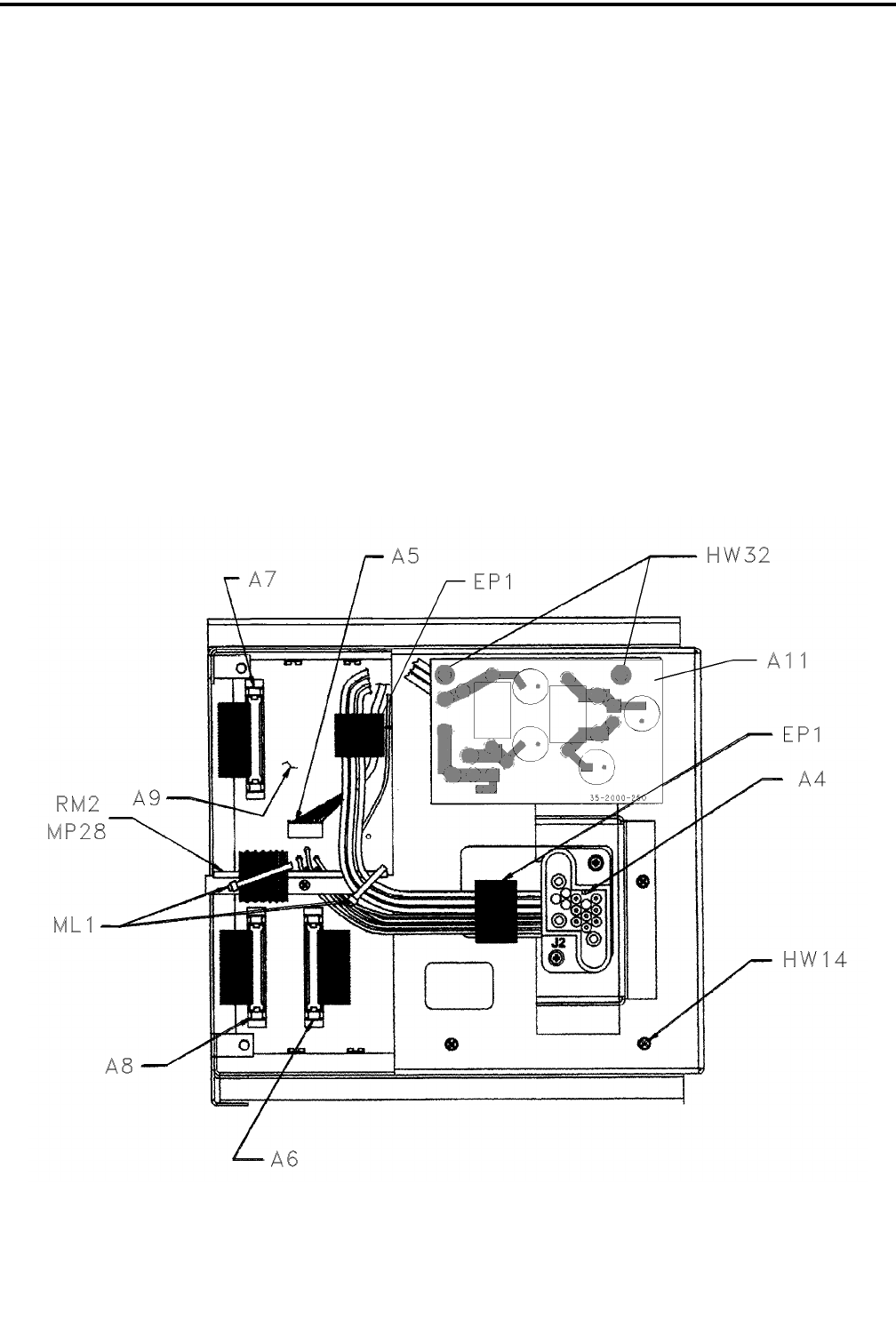
On the back of the card rack is the Backplane
with plug-in connectors to the cards and cables to the
RF modules, Power Supply and External Connector
Board.
Refer to the component layout and schematic dia-
gram in Section 10 for more information on the
repeater backplane.
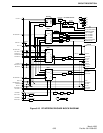
Figure 6-13 BACKPLANE CONNECTORS